Toyota Venza: Afs Ecu
Components
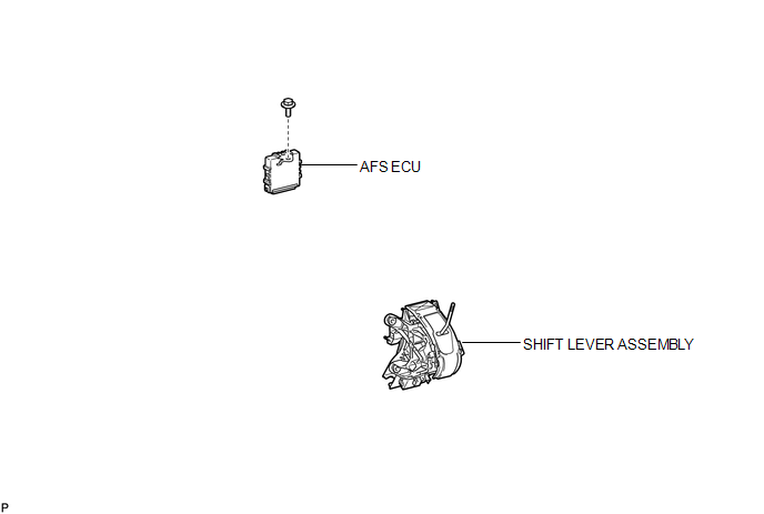
COMPONENTS
ILLUSTRATION
Installation
INSTALLATION
PROCEDURE
1. INSTALL AFS ECU
|
(a) Engage the guide. |
|
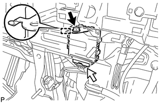
(b) Install the AFS ECU with the bolt.
(c) Connect the connector.
2. INSTALL SHIFT LEVER ASSEMBLY (for 2WD)
HINT:
Refer to the procedure from Install Shift Lever Assembly (See page
.gif) ).
).
3. INSTALL SHIFT LEVER ASSEMBLY (for AWD)
HINT:
Refer to the procedure from Install Shift Lever Assembly (See page
).
Removal
REMOVAL
PROCEDURE
1. REMOVE SHIFT LEVER ASSEMBLY (for 2WD)
HINT:
Refer to the procedure up to Remove Shift Lever Assembly (See page
.gif) ).
).
2. REMOVE SHIFT LEVER ASSEMBLY (for AWD)
HINT:
Refer to the procedure up to Remove Shift Lever Assembly (See page
).
3. REMOVE AFS ECU
|
(a) Disconnect the connector. |
|
.png)
(b) Remove the bolt.
(c) Disengage the guide and remove the AFS ECU.
 Lighting (ext)
...
 Automatic Light Control Sensor
Components
COMPONENTS
ILLUSTRATION
Removal
REMOVAL
PROCEDURE
1. REMOVE DEFROSTER NOZZLE GARNISH
2. REMOVE AUTOMATIC LIGHT CONTROL SENSOR
(a) Disengage the 2 claws and remov ...
Other materials about Toyota Venza:
Reassembly
REASSEMBLY
PROCEDURE
1. INSTALL NO. 2 STEERING RACK BOOT
(a) Apply lithium soap base glycol grease to the inside of the small
opening of a new No. 2 steering rack boot.
(b) Install the No. 2 ste ...
Traffic Information is not Displayed
PROCEDURE
1.
CHECK DISPLAY
(a) Check which communication is not being used for displaying traffic information.
HINT:
Display of traffic information received via HD traffic is given priority while
in an "HD Radio" ...
Radio Broadcast cannot be Received or Poor Reception
PROCEDURE
1.
CHECK RADIO AND DISPLAY RECEIVER ASSEMBLY
(a) Check the radio automatic station search function.
(1) Check the radio automatic station search function by activating it.
Result
Proceed to
...

0.1651