Toyota Venza: Adjustment
ADJUSTMENT
CAUTION / NOTICE / HINT
HINT:
- Use the same procedure for the RH side and LH side.
- The following procedure is for the LH side.
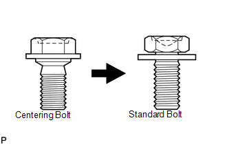
- Centering bolts are used to mount the door hinge to the vehicle body and door. The door cannot be adjusted with the centering bolts installed. Substitute the centering bolts with standard bolts (with washers) when making adjustments.
- Specified torque for standard bolts is shown in the standard bolt chart
(See page
.gif) ).
).
PROCEDURE
1. INSPECT BACK DOOR
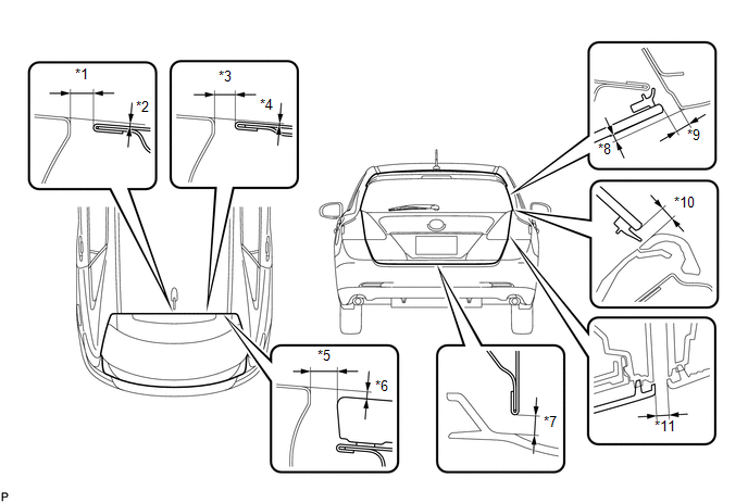
(a) Check that the clearance measurements of areas *1 through *11 are within each standard range.
 Standard Clearance
|
Area |
Measurement |
Area |
Measurement |
|---|---|---|---|
|
*1 |
6.3 to 9.3 mm (0.248 to 0.366 in.) |
*7 |
5.1 to 8.1 mm (0.201 to 0.319 in.) |
|
*2 |
0 to 3.0 mm (0 to 0.118 in.) |
*8 |
0.3 to 4.3 mm (0.0118 to 0.169 in.) |
|
*3 |
6.3 to 9.3 mm (0.248 to 0.366 in.) |
*9 |
4.0 to 7.0 mm (0.157 to 0.276 in.) |
|
*4 |
0.1 to 3.1 mm (0.00394 to 0.122 in.) |
*10 |
3.7 to 6.7 mm (0.146 to 0.264 in.) |
|
*5 |
6.6 to 9.6 mm (0.260 to 0.378 in.) |
*11 |
3.7 to 6.7 mm (0.146 to 0.264 in.) |
|
*6 |
0.1 to 3.1 mm (0.00394 to 0.122 in.) |
- |
- |
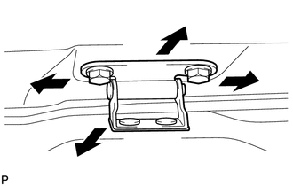
2. REMOVE REAR FLOOR FINISH PLATE
3. ADJUST BACK DOOR PANEL SUB-ASSEMBLY
|
(a) Before adjusting the upper end of the back door up and down or left and right, loosen the bolts. |
|
(b) Tighten the body side hinge after the adjustment.
Torque:
19 N·m {194 kgf·cm, 14 ft·lbf}
|
(c) Using a T40 "TORX" socket wrench, slightly loosen the striker mounting screws. |
|
(d) Using a brass bar and a hammer, hit the striker to adjust its position.
(e) Using a T40 "TORX" socket wrench, tighten the striker mounting screws after the adjustment.
Torque:
23 N·m {235 kgf·cm, 17 ft·lbf}
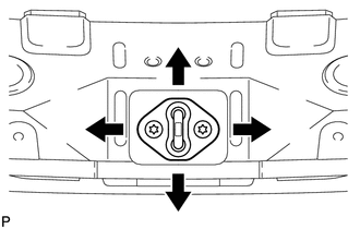
4. INSTALL REAR FLOOR FINISH PLATE
 Components
COMPONENTS
ILLUSTRATION
ILLUSTRATION
ILLUSTRATION
ILLUSTRATION
ILLUSTRATION
...
 Disassembly
DISASSEMBLY
PROCEDURE
1. REMOVE UPPER BACK WINDOW PANEL TRIM
(a) Disengage the 4 clips and 4 claws, and remove the upper back window
panel trim.
...
Other materials about Toyota Venza:
Speed Signal Circuit
DESCRIPTION
The headlight leveling ECU assembly receives the vehicle speed signal from the
combination meter assembly.
HINT:
A voltage of 12 V or 5 V is output from each ECU and then input to the
combination meter. The signal is changed to a p ...
Electronic Circuit Inspection Procedure
ELECTRONIC CIRCUIT INSPECTION PROCEDURE
1. BASIC INSPECTION
(a) WHEN MEASURING RESISTANCE OF ELECTRONIC PARTS
(1) Unless otherwise stated, all resistance measurements are standard values
measured at an ambient temperature of 20°C (68°F). Resistance meas ...
ABS Warning Light does not Come ON
DESCRIPTION
The skid control ECU is connected to the combination meter via CAN communication.
WIRING DIAGRAM
Refer to ABS Warning Light Remains ON (See page
).
PROCEDURE
1.
CHECK CAN COMMUNICATION SYSTEM
(a) Check if a C ...

0.1334