Toyota Venza: Accessory Meter
Components
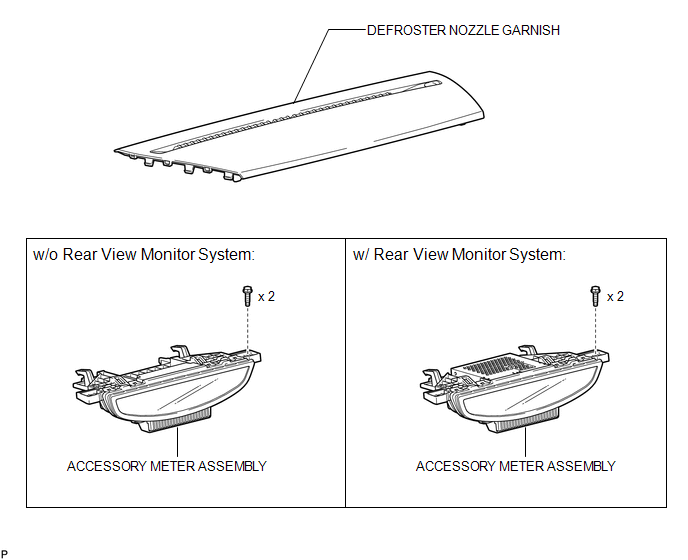
COMPONENTS
ILLUSTRATION
Installation
INSTALLATION
PROCEDURE
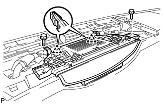
1. INSTALL ACCESSORY METER ASSEMBLY (w/o Rear View Monitor System)
|
(a) Connect the connector. |
|
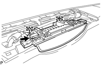
(b) Engage the 2 clamps.
|
(c) Engage the 2 clips. |
|
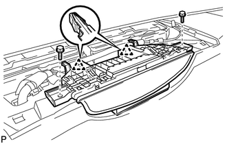
(d) Install the accessory meter assembly with the 2 bolts.
2. INSTALL ACCESSORY METER ASSEMBLY (w/ Rear View Monitor System)
|
(a) Connect the connectors. |
|
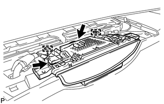
(b) Engage the 2 clamps.
|
(c) Engage the 2 clips. |
|
(d) Install the accessory meter assembly with the 2 bolts.
3. INSTALL DEFROSTER NOZZLE GARNISH
.gif)
Removal
REMOVAL
PROCEDURE
1. REMOVE DEFROSTER NOZZLE GARNISH
.gif)
2. REMOVE ACCESSORY METER ASSEMBLY (w/o Rear View Monitor System)
|
(a) Remove the 2 bolts. |
|
.png)
(b) Disengage the 2 clips.
|
(c) Disengage the 2 clamps. |
|
.png)
(d) Disconnect the connector and remove the accessory meter assembly.
3. REMOVE ACCESSORY METER ASSEMBLY (w/ Rear View Monitor System)
|
(a) Remove the 2 bolts. |
|
.png)
(b) Disengage the 2 clips.
|
(c) Disengage the 2 clamps. |
|
.png)
(d) Disconnect the connectors and remove the accessory meter assembly.

 Clock System
...
Other materials about Toyota Venza:
Reassembly
REASSEMBLY
CAUTION / NOTICE / HINT
HINT:
Perform "Inspection After Repair" after replacing the piston or piston ring (See
page ).
PROCEDURE
1. INSTALL STUD BOLT
NOTICE:
If a stud bolt is deformed or the threads are damaged, replace it.
(a) ...
Problem Symptoms Table
PROBLEM SYMPTOMS TABLE
HINT:
Use the table below to help determine the cause of problem symptoms.
If multiple suspected areas are listed, the potential causes of the symptoms
are listed in order of probability in the "Suspected Area" ...
Removal
REMOVAL
CAUTION / NOTICE / HINT
HINT:
Use the same procedure for the RH side and LH side.
The procedure listed below is for the LH side.
PROCEDURE
1. PRECAUTION
CAUTION:
Be sure to read Precaution thoroughly before servicing (See page
...

0.1611