Toyota Venza: Parts Location
PARTS LOCATION
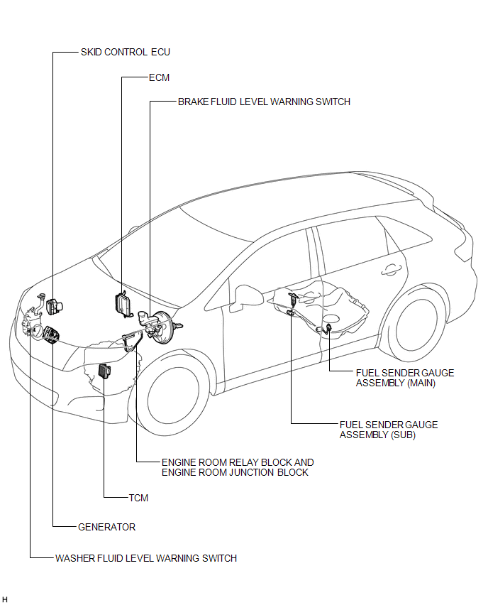
ILLUSTRATION
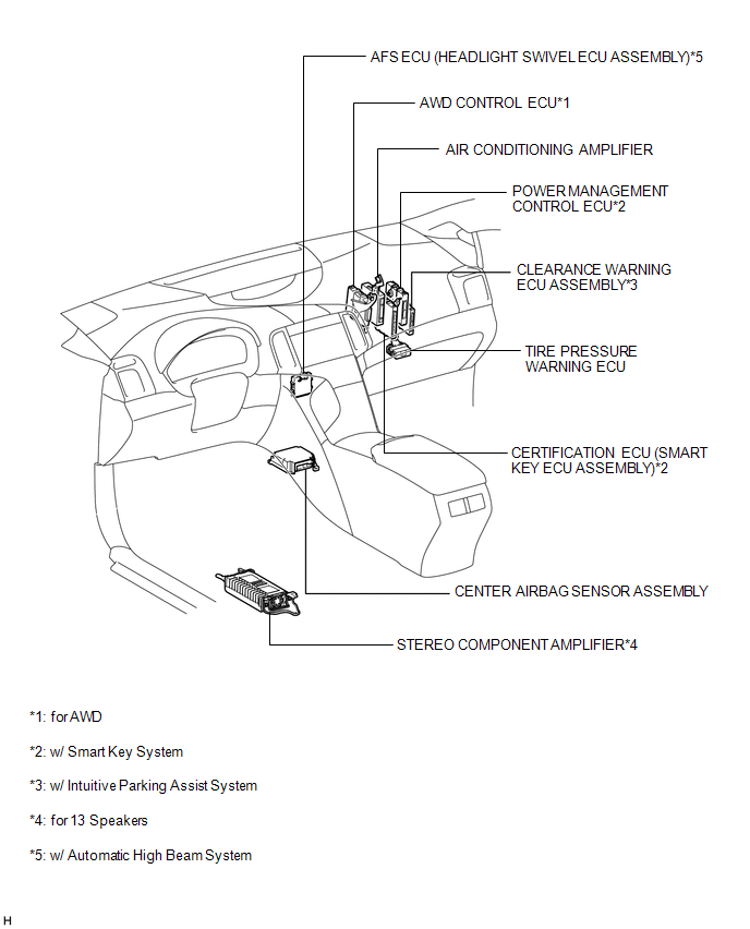
ILLUSTRATION

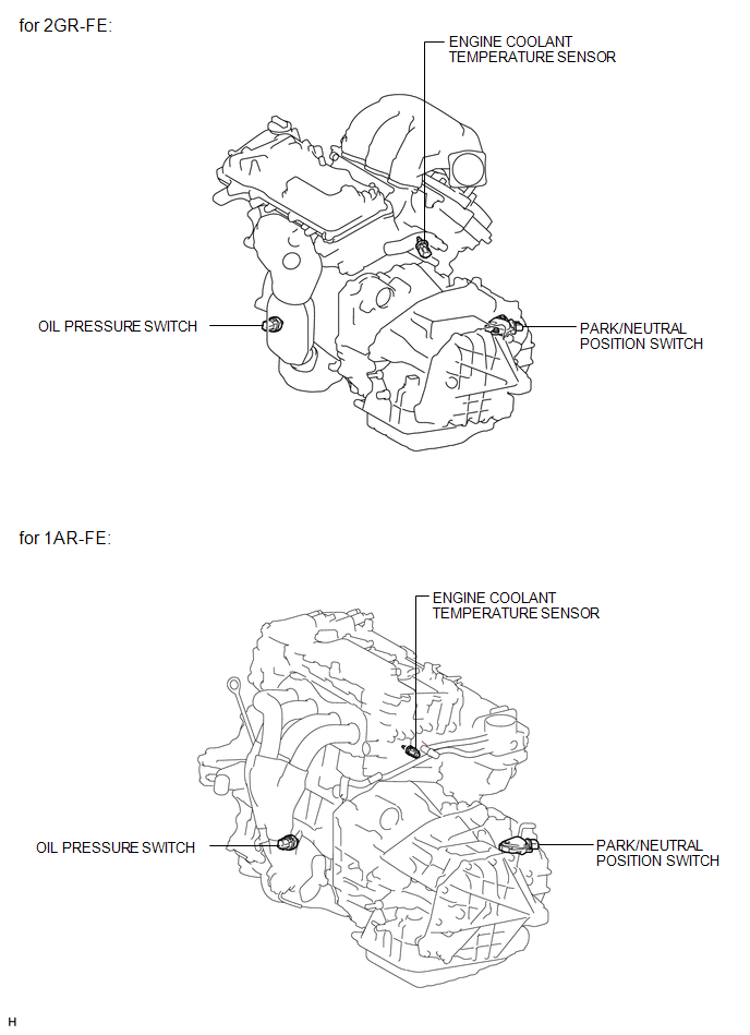
ILLUSTRATION
ILLUSTRATION

 Precaution
PRECAUTION
NOTICE:
When disconnecting the cable from the negative (-) battery terminal, initialize
the following systems after the cable is reconnected.
System Name
See Proc ...
Other materials about Toyota Venza:
BUS IC Communication Malfunction (B1497/97)
DESCRIPTION
The air conditioning harness connects the A/C amplifier and each servo. The A/C
amplifier supplies power and sends operation instructions to each servo through
the air conditioning harness. Each servo sends the damper position information to
...
Terminals Of Ecu
TERMINALS OF ECU
HINT:
Check from the rear of the connector while it is connected to the components.
1. NAVIGATION RECEIVER ASSEMBLY
Terminal No. (Symbol)
Wiring Color
Terminal Description
Condition
...
Electrical Key Oscillator(for Rear Floor)
Components
COMPONENTS
ILLUSTRATION
Removal
REMOVAL
PROCEDURE
1. REMOVE TONNEAU COVER ASSEMBLY (w/ Tonneau Cover)
2. REMOVE DECK BOARD ASSEMBLY
3. REMOVE NO. 3 DECK BOARD SUB-ASSEMBLY
4. REMOVE DECK SIDE TRIM BOX LH
5. REMOVE NO. 2 D ...

0.1274