
Toyota Venza: Instrument panel
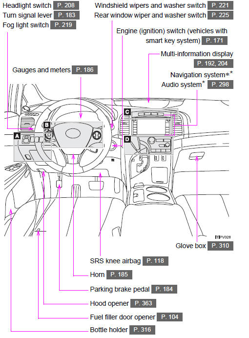
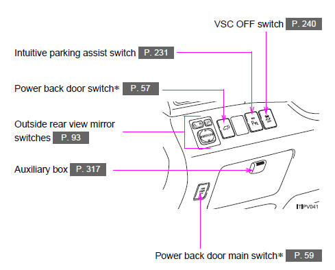

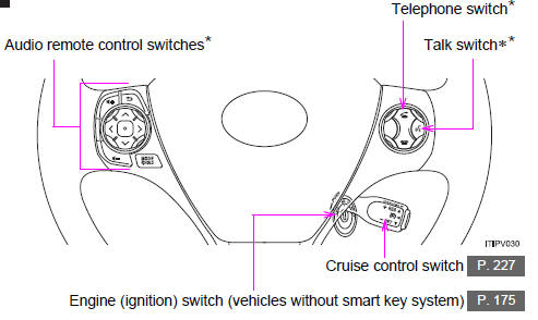
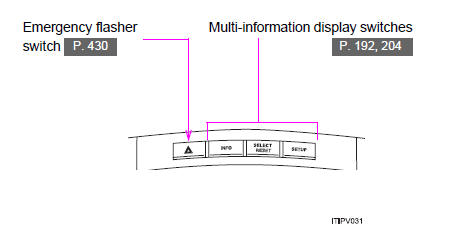

 Interior
...
 Luggage compartment
For your information
Main Owner’s Manual
Please note that this manual applies to all models and explains all equipment,
including options. Therefore, you may find some explanations for equip ...
Other materials about Toyota Venza:
Registration
REGISTRATION
CAUTION / NOTICE / HINT
NOTICE:
When the automatic transaxle is replaced, the transaxle compensation
code must be input into the TCM (proceed to Procedure 1). After the automatic
transaxle is reinstalled, the Quick Response (QR) ...
Inspection
INSPECTION
PROCEDURE
1. INSPECT GENERATOR PULLEY WITH CLUTCH
(a) Hold the center of the pulley, and confirm that the outer ring turns
counterclockwise and does not turn clockwise.
Text in Illustration
*1
...
Noise Occurs
PROCEDURE
1.
NOISE CONDITION
(a) Check from which direction the noise comes (front left or right, or rear
left or right).
OK:
The location of the noise source can be determined.
NG
GO TO STEP 3
...

0.1691