Toyota Venza: Terminals Of Ecu
TERMINALS OF ECU
1. CHECK POWER BACK DOOR ECU (POWER BACK DOOR MOTOR UNIT)
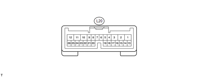
(a) Disconnect the L20 ECU connector.
(b) Measure the voltage and resistance according to the value(s) in the table below.
|
Tester Connection |
Wiring Color |
Terminal Description |
Condition |
Specified Condition |
|---|---|---|---|---|
|
L20-10 (ECUB) - Body ground |
P - Body ground |
Battery power supply |
Always |
11 to 14 V |
|
L20-12 (B) - Body ground |
LG - Body ground |
Battery power supply |
Always |
11 to 14 V |
|
L20-8 (IG) - Body ground |
SB - Body ground |
IG power supply |
Ignition switch ON |
11 to 14 V |
|
L20-8 (IG) - Body ground |
SB - Body ground |
IG power supply |
Ignition switch off |
Below 1 V |
|
L20-17 (MSW) - Body ground |
R - Body ground |
Power back door main switch signal |
Power back door main switch not pushed |
Below 1 Ω |
|
L20-17 (MSW) - Body ground |
R - Body ground |
Power back door main switch signal |
Power back door main switch pushed |
10 kΩ or higher |
|
L20-4 (DS1) - Body ground |
L - Body ground |
Power back door closer switch signal |
Power back door closer switch on |
Below 1 Ω |
|
L20-4 (DS1) - Body ground |
L - Body ground |
Power back door closer switch signal |
Power back door closer switch off |
10 kΩ or higher |
|
L20-15 (OSL) - L20-14 (OSE) |
Y - V |
Power back door touch sensor LH signal |
Power back door touch sensor LH not pressed |
950 to 1050 Ω |
|
L20-15 (OSL) - L20-14 (OSE) |
Y - V |
Power back door touch sensor LH signal |
Back door touch sensor LH pressed |
Below 100 Ω |
|
L20-13 (OSR) - L20-14 (OSE) |
R - V |
Power back door touch sensor RH signal |
Back door touch sensor RH not pressed |
950 to 1050 Ω |
|
L20-13 (OSR) - L20-14 (OSE) |
R - V |
Power back door touch sensor RH signal |
Power back door touch sensor RH pressed |
Below 100 Ω |
|
L20-11 (GND) - Body ground |
W-B - Body ground |
Ground |
Always |
Below 1 Ω |
If the result is not as specified, there may be a malfunction on the wire harness side.
(c) Reconnect the L20 ECU connector.
(d) Initialize the power back door system (See page
.gif) ).
).
(e) Measure the voltage according to the value(s) in the table below.
|
Tester Connection |
Wiring Color |
Terminal Description |
Condition |
Specified Condition |
|---|---|---|---|---|
|
L20-17 (MSW) - Body ground |
R - Body ground |
Power back door main switch signal |
Power back door main switch not pushed |
Below 1 V |
|
L20-17 (MSW) - Body ground |
R - Body ground |
Power back door main switch signal |
Power back door main switch pushed |
Pulse generation |
|
L20-26 (BZR+) - Body ground |
SB - Body ground |
Power back door warning buzzer signal input |
Back door warning buzzer sounding |
Pulse generation |
|
L20-26 (BZR+) - Body ground |
SB - Body ground |
Power back door warning buzzer signal input |
Back door warning buzzer stopped |
Below 1 V |
|
L20-2 (DC+) - L20-1 (DC-) |
L - G |
Power back door lock motor signal |
Back door lock motor operating |
11 to 14 V |
|
L20-2 (DC+) - L20-1 (DC-) |
L - G |
Power back door lock motor signal |
Back door lock motor stopped |
Below 1 V |
|
L20-4 (DS1) - Body ground |
L - Body ground |
Power back door closer switch signal |
Power back door closer switch on |
Below 1 V |
|
L20-4 (DS1) - Body ground |
L - Body ground |
Power back door closer switch signal |
Power back door closer switch off |
Pulse generation |
|
L20-15 (OSL) - L20-14 (OSE) |
Y - V |
Power back door touch sensor LH signal |
Power back door touch sensor LH not pressed |
4 to 6 V |
|
L20-15 (OSL) - L20-14 (OSE) |
Y - V |
Power back door touch sensor LH signal |
Back door touch sensor LH pressed |
Below 1 V |
|
L20-13 (OSR) - L20-14 (OSE) |
R - V |
Power back door touch sensor RH signal |
Back door touch sensor RH not pressed |
4 to 6 V |
|
L20-13 (OSR) - L20-14 (OSE) |
R - V |
Power back door touch sensor RH signal |
Power back door touch sensor RH pressed |
Below 1 V |
If the result is not as specified, the ECU may have a malfunction.
2. CHECK MAIN BODY ECU (DRIVER SIDE JUNCTION BLOCK ASSEMBLY)
.png)
(a) Disconnect the D49 and 2F connectors.
(b) Measure the resistance according to the value(s) in the table below.
|
Tester Connection |
Wiring Color |
Terminal Description |
Condition |
Specified Condition |
|---|---|---|---|---|
|
D49-2 (BDSU) - Body ground |
GR - Body ground |
Back door opener switch signal circuit |
Back door opener switch on |
Below 1 Ω |
|
D49-2 (BDSU) - Body ground |
GR - Body ground |
Back door opener switch signal circuit |
Back door opener switch off |
10 kΩ or higher |
|
D49-26 (PBDS) - Body ground |
BR - Body ground |
Power back door open / close switch signal circuit |
Power back door open / close switch on |
Below 1 Ω |
|
D49-26 (PBDS) - Body ground |
BR - Body ground |
Power back door open / close switch signal circuit |
Power back door open / close switch off |
10 kΩ or higher |
|
2F-16 (GND1) - Body ground |
W-B - Body ground |
Ground |
Always |
Below 1 Ω |
If the result is not as specified, there may be a malfunction on the wire harness side.
(c) Reconnect the D49 and 2F connectors.
(d) Measure the voltage according to the value(s) in the table below.
|
Tester Connection |
Wiring Color |
Terminal Description |
Condition |
Specified Condition |
|---|---|---|---|---|
|
D49-26 (PBDS) - Body ground |
BR - Body ground |
Power back door control switch signal |
Power back door control switch on |
Below 1 V |
|
D49-26 (PBDS) - Body ground |
BR - Body ground |
Power back door control switch signal |
Power back door control switch off |
Pulse generation |
|
D49-2 (BDSU) - Body ground |
GR - Body ground |
Back door opener switch signal |
Back door opener switch on |
Below 1 V |
|
D49-2 (BDSU) - Body ground |
GR - Body ground |
Back door opener switch signal |
Back door opener switch off |
Pulse generation |
If the result is not as specified, the ECU may have a malfunction.
 Diagnosis System
DIAGNOSIS SYSTEM
1. DESCRIPTION
(a) The power back door ECU (power back door motor unit) controls the power back
door system functions. Power back door system data and Diagnostic Trouble Code (DTC ...
 Dtc Check / Clear
DTC CHECK / CLEAR
1. CHECK DTC
(a) Connect the Techstream to the DLC3.
(b) Turn the ignition switch to ON.
(c) Turn the Techstream on.
(d) Read the DTCs by following the directions on the Techstr ...
Other materials about Toyota Venza:
Communication Malfunction No. 1 (B2797)
DESCRIPTION
This DTC is stored when an error occurs in communication between the transponder
key amplifier and the transponder key ECU assembly.
HINT:
Some noise is found in the communication line.
DTC No.
DTC Detection Condition
...
Disposal
DISPOSAL
PROCEDURE
1. DISPOSE OF FRONT SHOCK ABSORBER ASSEMBLY
(a) Position the front shock absorber assembly level with the piston
rod fully extended. Using a drill, make a hole in the cylinder between A
and B as shown in the illustratio ...
Transmission Fluid Pressure Sensor / Switch "E" Circuit Low (P0989,P0990)
DESCRIPTION
ATF pressure switch No. 3 is installed in the lock-up solenoid ATF output passage
and is used to detect a malfunction in the lock-up solenoid.
DTC No.
DTC Detection Condition
Trouble Area
P0989
...

0.1321