Toyota Venza: Replacement
REPLACEMENT
PROCEDURE
1. REPLACE INTAKE VALVE GUIDE BUSH
(a) Heat the cylinder head to approximately 80 to 100°C (176 to 212°F).
(b) Place the cylinder head on wooden blocks.
|
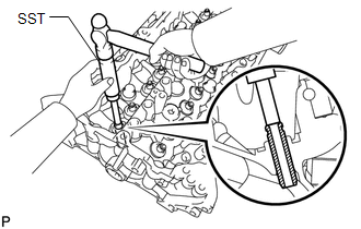
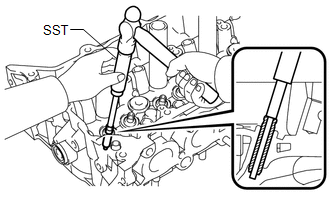
(c) Using SST and a hammer, tap out the valve guide bush. SST: 09201-01055 SST: 09950-70010 09951-07100 |
|
|
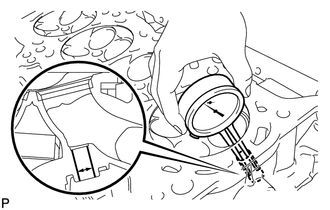
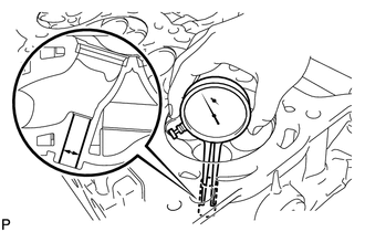
(d) Using a caliper gauge, measure the bush bore diameter of the cylinder head. Standard bush bore diameter: 10.285 to 10.306 mm (0.405 to 0.406 in.) If the bush bore diameter of the cylinder head is between 10.285 and 10.306 mm (0.405 and 0.406 in.), proceed to the next step. If the bush bore diameter of the cylinder head is 10.356 mm (0.408 in.) or more, replace the cylinder head |
|
(e) Select a new guide bush (STD or O/S 0.05), and measure its diameter.
(f) Machine the bush bore of the cylinder head to the diameter of the selected guide bush.
Bush Bore Diameter:
|
Bush Size |
Specified Condition |
|---|---|
|
STD |
10.333 to 10.344 mm (0.4068 to 0.4072 in.) |
|
O/S 0.05 |
10.383 to 10.394 mm (0.4088 to 0.4092 in.) |
Standard bush length:
41.3 to 41.7 mm (1.626 to 1.642 in.)
(g) Heat the cylinder head to approximately 80 to 100°C (176 to 212°F).
|
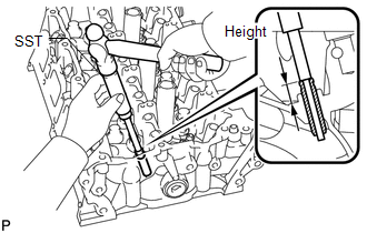
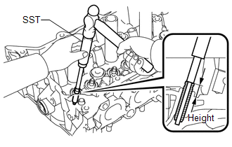
(h) Using SST and a hammer, tap in the selected guide bush to the standard protrusion height. SST: 09201-10000 09201-01050 SST: 09950-70010 09951-07100 Standard protrusion height: 14.8 to 15.2 mm (0.582 to 0.598 in.) |
|
|
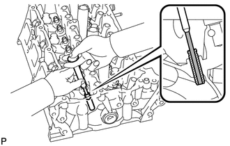
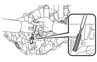
(i) Using a sharp 5.5 mm reamer, ream the guide bush to obtain the standard oil clearance between the guide bush and valve stem. Standard oil clearance: 0.025 to 0.060 mm (0.000984 to 0.00236 in.) |
|
2. REPLACE EXHAUST VALVE GUIDE BUSH
(a) Heat the cylinder head to approximately 80 to 100°C (176 to 212°F).
(b) Place the cylinder head on wooden blocks.
|
(c) Using SST and a hammer, tap out the valve guide bush. SST: 09201-01055 SST: 09950-70010 09951-07100 |
|
|
(d) Using a caliper gauge, measure the bush bore diameter of the cylinder head. Standard bush bore diameter: 10.285 to 10.306 mm (0.405 to 0.406 in.) If the bush diameter of the cylinder head is between 10.285 and 10.306 mm (0.405 and 0.406 in.), proceed to the next step. If the bush bore diameter of the cylinder head is 10.356 mm (0.408 in.) or more, replace the cylinder head. |
|
(e) Select a new guide bush (STD or O/S 0.05), and measure its diameter.
(f) Machine the bush bore of the cylinder head to the diameter of the selected guide bush.
Bush Bore Diameter:
|
Bush Size |
Specified Condition |
|---|---|
|
STD |
10.333 to 10.344 mm (0.4068 in 0.4072 in.) |
|
O/S 0.05 |
10.383 to 10.394 mm (0.4088 to 0.4092 in.) |
Standard bush length:
46.8 to 47.2 mm (1.843 to 1.858 in.)
(g) Heat the cylinder head to approximately 80 to 100°C (176 to 212°F).
|
(h) Using SST and a hammer, tap in the selected guide bush to the standard protrusion height. SST: 09201-10000 09201-01050 SST: 09950-70010 09951-07100 Standard protrusion height: 14.2 to 14.6 mm (0.559 to 0.575 in.) |
|
|
(i) Using a sharp 5.5 mm reamer, ream the guide bush to obtain the standard oil clearance between the guide bush and valve stem. Standard oil clearance: 0.030 to 0.065 mm (0.00118 to 0.00256 in.) |
|
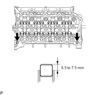
3. REPLACE RING PIN
NOTICE:
It is not necessary to remove the ring pin unless it is being replaced.
(a) Remove the ring pins.
|
(b) Using a plastic-faced hammer, tap in new ring pins to the cylinder head. Standard protrusion height: 6.5 to 7.5 mm (0.256 to 0.295 in.) |
|
 Inspection
INSPECTION
PROCEDURE
1. INSPECT CYLINDER HEAD SUB-ASSEMBLY
(a) Using a precision straightedge and feeler gauge, measure the warpage of the
contact surfaces where the cylinder head contacts the cy ...
 Reassembly
REASSEMBLY
CAUTION / NOTICE / HINT
HINT:
Perform "Inspection After Repair" after replacing the cylinder head sub-assembly
(See page ).
PROCEDURE
1. INSTALL SPARK PLUG TUBE
HINT:
Wh ...
Other materials about Toyota Venza:
Lost Communication with Front Satellite Sensor Bus (B161A/8A)
DESCRIPTION
The front collision sensor circuit (front airbag sensor RH circuit and front
airbag sensor LH circuit) is composed of the center airbag sensor assembly, front
airbag sensor RH and front airbag sensor LH.
The front airbag sensor RH or front ai ...
Noise Occurs from Generator while Engine is Running
PROCEDURE
1.
CHECK LOOSENESS OF V-RIBBED BELT
(a) Check the tension of the belt by pushing it down with a finger.
OK:
The tension of the belt is enough.
NG
REPLACE V-RIBBED BELT TENSIONER ASSEMBLY
...
Installation
INSTALLATION
PROCEDURE
1. INSTALL PARKING BRAKE SWITCH ASSEMBLY
(a) Install the parking brake switch assembly with the screw.
Torque:
0.9 N·m {9 kgf·cm, 8 in·lbf}
2. INSTALL PARKING BRAKE ...

0.161