Toyota Venza: System Diagram
SYSTEM DIAGRAM
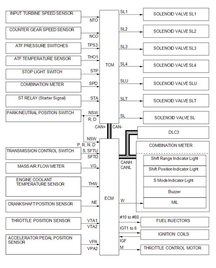
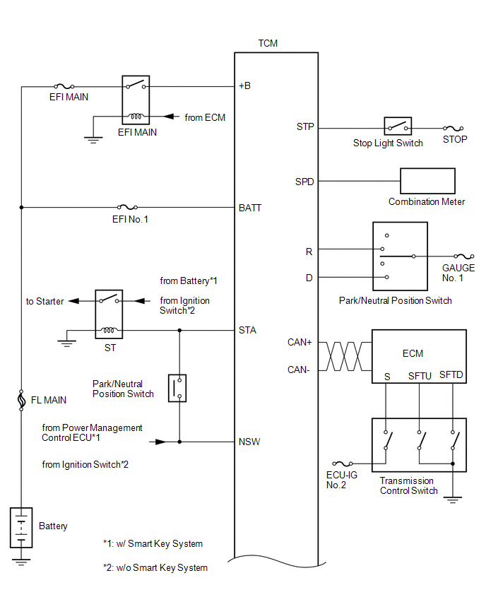
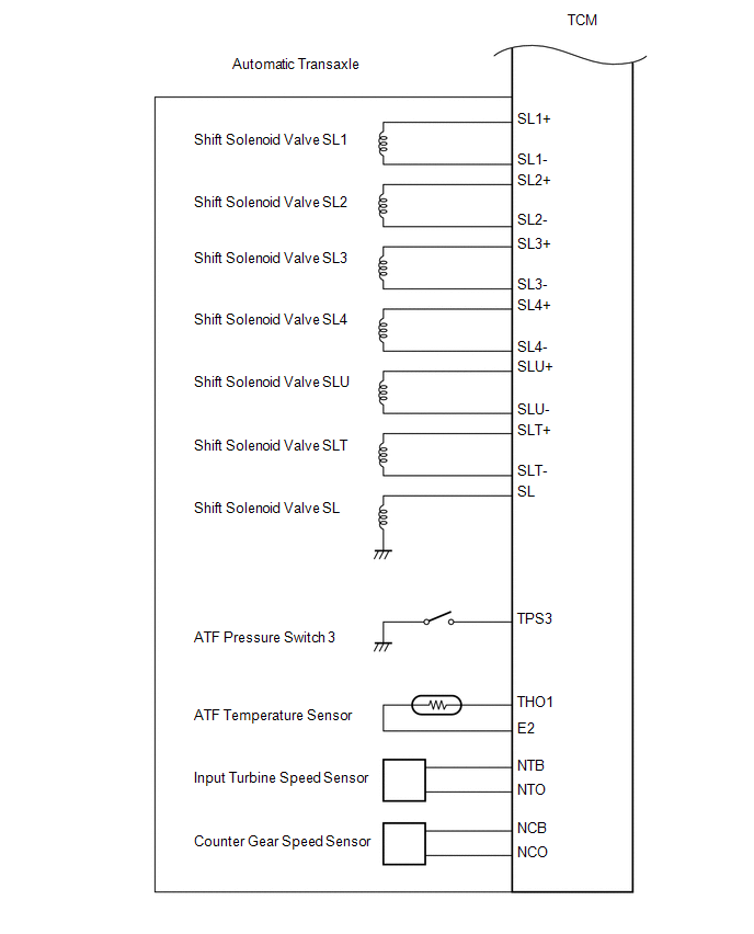
The configuration of the electronic control system in the U660E automatic transaxle is as shown in the following chart.
 System Description
SYSTEM DESCRIPTION
1. SYSTEM DESCRIPTION
(a) The Electronic Controlled Automatic Transaxle (ECT) is an automatic transaxle
that has its shift timing electronically controlled by the Transmission C ...
 How To Proceed With Troubleshooting
CAUTION / NOTICE / HINT
HINT:
The TCM of this system is connected to the CAN communication system.
Therefore, before starting troubleshooting, make sure to check that there
is no tro ...
Other materials about Toyota Venza:
Automatic anti-glare function
Responding to the level of brightness of the headlights of vehicles behind, the
reflected light is automatically reduced.
Changing automatic anti-glare function mode ON/OFF
When the automatic anti-glare function is in ON mode, the indicator illuminates.
...
Fail-safe Chart
FAIL-SAFE CHART
1. POWER WINDOW OPERATION IN FAIL-SAFE MODE
HINT:
If the pulse sensor built into the power window regulator motor malfunctions,
the power window control system enters fail-safe mode.
(a) The power window control system prohibits the follo ...
Passenger Side Buckle Switch Circuit Malfunction (B1771)
DESCRIPTION
The passenger side buckle switch circuit consists of the occupant classification
ECU and front seat inner belt assembly RH.
DTC B1771 is recorded when a malfunction is detected in the passenger side buckle
switch circuit.
Troubleshoot DTC B1 ...

0.1592