Toyota Venza: System Diagram
SYSTEM DIAGRAM
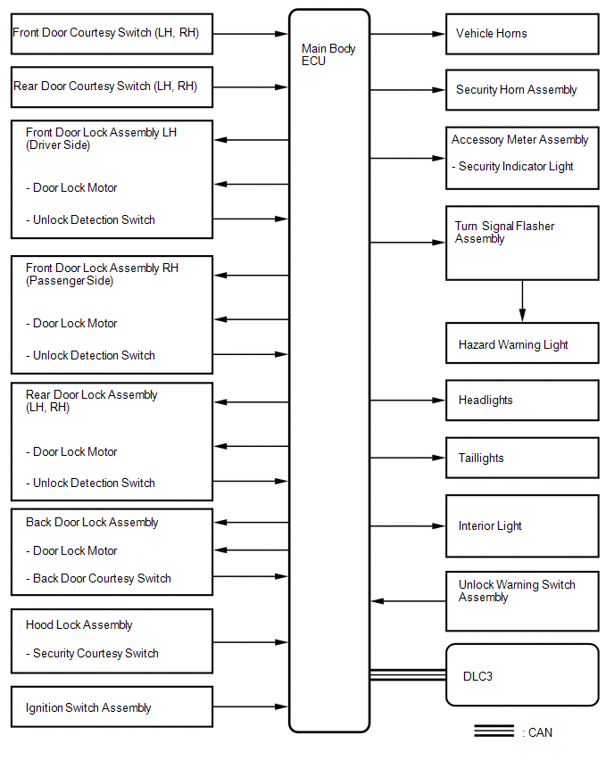
 System Description
SYSTEM DESCRIPTION
1. OUTLINE OF THEFT DETERRENT SYSTEM
The theft deterrent system can be set by locking the doors using the
transmitter or key, or by opening and closing the doors (for d ...
 How To Proceed With Troubleshooting
CAUTION / NOTICE / HINT
HINT:
Use this procedure to troubleshoot the theft deterrent system.
*: Use the Techstream.
PROCEDURE
1.
VEHICLE BROUGHT TO WORKSHO ...
Other materials about Toyota Venza:
Reassembly
REASSEMBLY
PROCEDURE
1. INSTALL FRONT SEAT WIRE RH (for Front Passenger Side)
(a) Engage each clamp and install the front seat wire RH.
2. INSTALL OCCUPANT CLASSIFICATION ECU (for Front Passenger Side)
3. INSTALL SEAT POSITION SENSOR
4. INSTALL SEA ...
Headlight Signal Circuit
DESCRIPTION
The headlight leveling ECU assembly detects the low beam headlights status.
WIRING DIAGRAM
CAUTION / NOTICE / HINT
NOTICE:
First check that the low beam headlights operate normally.
PROCEDURE
1.
CHECK HARNESS AND CON ...
Inspection
INSPECTION
PROCEDURE
1. INSPECT FRONT DRIVE SHAFT ASSEMBLY
(a) Check whether the drive shaft dimensions are within the following
specifications.
Text in Illustration
*A
LH
*B
...

0.1811