Toyota Venza: System Diagram
SYSTEM DIAGRAM
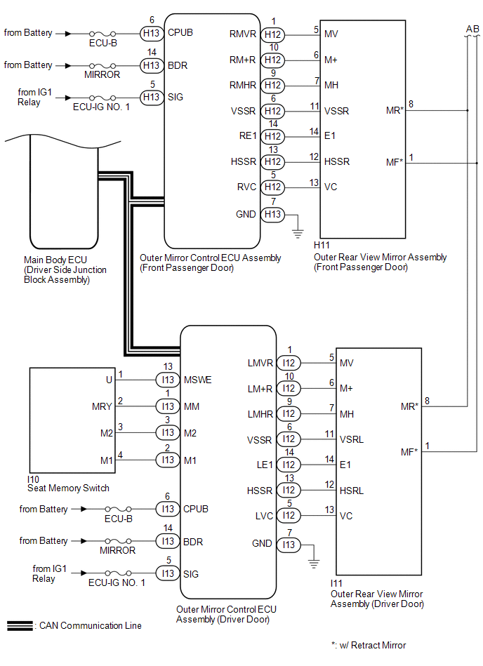
1. MIRROR CONTROL SYSTEM
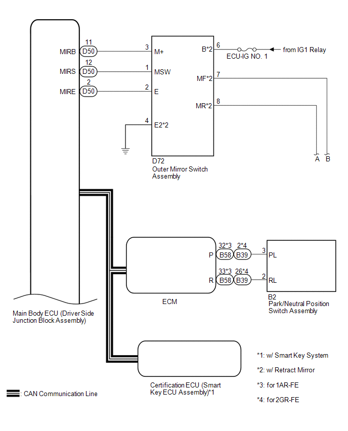
 Communication Table
|
Sender |
Receiver |
Signal / Signal Condition |
Line |
|---|---|---|---|
|
Main body ECU (driver side junction block assembly) |
Outer mirror control ECU assembly (driver door) |
Ignition switch signal / ON or off |
CAN |
|
Main body ECU (driver side junction block assembly) |
Outer mirror control ECU assembly (front passenger door) |
Ignition switch signal / ON or off |
CAN |
|
Main body ECU (driver side junction block assembly) |
Outer mirror control ECU assembly (driver door) |
Ignition switch ACC signal / ACC or off |
CAN |
|
Main body ECU (driver side junction block assembly) |
Outer mirror control ECU assembly (front passenger door) |
Ignition switch ACC signal / ACC or off |
CAN |
|
Main body ECU (driver side junction block assembly) |
Outer mirror control ECU assembly (driver door) |
Outer mirror RH select switch signal / on or off |
CAN |
|
Main body ECU (driver side junction block assembly) |
Outer mirror control ECU assembly (front passenger door) |
Outer mirror RH select switch signal / on or off |
CAN |
|
Main body ECU (driver side junction block assembly) |
Outer mirror control ECU assembly (driver door) |
Outer mirror LH select switch signal / on or off |
CAN |
|
Main body ECU (driver side junction block assembly) |
Outer mirror control ECU assembly (front passenger door) |
Outer mirror LH select switch signal / on or off |
CAN |
|
Main body ECU (driver side junction block assembly) |
Outer mirror control ECU assembly (driver door) |
Mirror adjust switch signal (Right) / on or off |
CAN |
|
Main body ECU (driver side junction block assembly) |
Outer mirror control ECU assembly (front passenger door) |
Mirror adjust switch signal (Right) / on or off |
CAN |
|
Main body ECU (driver side junction block assembly) |
Outer mirror control ECU assembly (driver door) |
Mirror adjust switch signal (Left) / on or off |
CAN |
|
Main body ECU (driver side junction block assembly) |
Outer mirror control ECU assembly (front passenger door) |
Mirror adjust switch signal (Left) / on or off |
CAN |
|
Main body ECU (driver side junction block assembly) |
Outer mirror control ECU assembly (driver door) |
Mirror adjust switch signal (Up) / on or off |
CAN |
|
Main body ECU (driver side junction block assembly) |
Outer mirror control ECU assembly (front passenger door) |
Mirror adjust switch signal (Up) / on or off |
CAN |
|
Main body ECU (driver side junction block assembly) |
Outer mirror control ECU assembly (driver door) |
Mirror adjust switch signal (Down) / on or off |
CAN |
|
Main body ECU (driver side junction block assembly) |
Outer mirror control ECU assembly (front passenger door) |
Mirror adjust switch signal (Down) / on or off |
CAN |
|
Main body ECU (driver side junction block assembly) |
Outer mirror control ECU assembly (driver door) |
Mirror position request signal / memory request, reverse memory request, memory call request, reverse request or return request |
CAN |
|
Main body ECU (driver side junction block assembly) |
Outer mirror control ECU assembly (front passenger door) |
Mirror position request signal / memory request, reverse memory request, memory call request, reverse request or return request |
CAN |
|
Outer mirror control ECU assembly (driver door) |
Main body ECU (driver side junction block assembly) |
Outer mirror LH state signal / Manual operation, memory operation, reverse operation or return operation |
CAN |
|
Outer mirror control ECU assembly (front passenger door) |
Main body ECU (driver side junction block assembly) |
Outer mirror RH state signal / Manual operation, memory operation, reverse operation or return operation |
CAN |
|
Outer mirror control ECU assembly (driver door) |
Main body ECU (driver side junction block assembly) |
Seat memory switch signal / M1 switch, M2 switch or SET switch |
CAN |
2. MIRROR HEATER SYSTEM
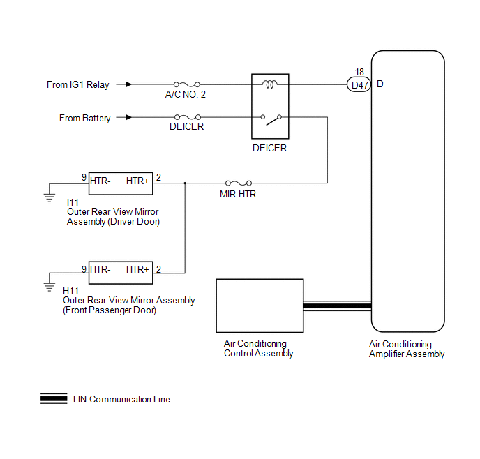 Communication Table
|
Transmitting ECU |
Receiving ECU |
Signal |
Communication Method |
|---|---|---|---|
|
Air Conditioning Control Assembly |
Air Conditioning Amplifier Assembly |
Rear window defogger switch signal |
LIN |
 System Description
SYSTEM DESCRIPTION
1. POWER MIRROR CONTROL SYSTEM DESCRIPTION
(a) This system has the following functions: power retract mirror function*,
reverse shift-linked function, electrical remote control ...
 How To Proceed With Troubleshooting
CAUTION / NOTICE / HINT
HINT:
Use the following procedure to troubleshoot the power mirror control
system.
*: Use the Techstream.
PROCEDURE
1.
VEHICLE ...
Other materials about Toyota Venza:
Open in Outside Luggage Compartment Electrical Key Antenna Circuit (B27A8)
DESCRIPTION
The certification ECU (smart key ECU assembly) generates a request signal and
sends it to the outside electrical key oscillator (for rear side). To detect the
key near the driver door, the outside electrical key oscillator (for rear side)
cr ...
Skid Control ECU Communication Stop Mode
DESCRIPTION
Detection Item
Symptom
Trouble Area
Skid Control ECU Communication Stop Mode
"ABS/VSC/TRAC" is not displayed on "CAN Bus Check" screen of
the Techstr ...
Components
COMPONENTS
ILLUSTRATION
ILLUSTRATION
ILLUSTRATION
ILLUSTRATION
ILLUSTRATION
ILLUSTRATION
...

0.1179