Toyota Venza: Stereo Component Amplifier
Components
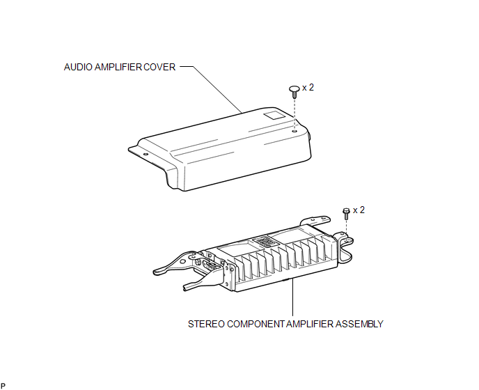
COMPONENTS
ILLUSTRATION
Removal
REMOVAL
PROCEDURE
1. REMOVE FRONT SEAT ASSEMBLY RH (for Manual Seat)
HINT:
Use the same procedure for the RH side and the LH side (See page
.gif) ).
).
2. REMOVE FRONT SEAT ASSEMBLY RH (for Power Seat)
HINT:
Use the same procedure for the RH side and the LH side (See page
).
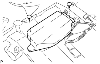
3. REMOVE AUDIO AMPLIFIER COVER
|
(a) Using a clip remover, remove the 2 clips and audio amplifier cover. |
|
4. REMOVE STEREO COMPONENT AMPLIFIER ASSEMBLY
|
(a) Disconnect the 4 connectors. |
|
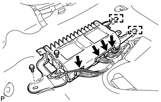
(b) Remove the 2 bolts.
(c) Disengage the 2 guides and remove the stereo component amplifier assembly.
Installation
INSTALLATION
PROCEDURE
1. INSTALL STEREO COMPONENT AMPLIFIER ASSEMBLY
|
(a) Engage the 2 guides. |
|
.png)
(b) Install the stereo component amplifier assembly with the 2 bolts.
(c) Connect the 4 connectors.
2. INSTALL AUDIO AMPLIFIER COVER
|
(a) Install the audio amplifier cover with the 2 clips. |
|
.png)
3. INSTALL FRONT SEAT ASSEMBLY RH (for Manual Seat)
HINT:
Use the same procedure for the RH side and the LH side (See page
.gif) ).
).
4. INSTALL FRONT SEAT ASSEMBLY RH (for Power Seat)
HINT:
Use the same procedure for the RH side and the LH side (See page
).
 Installation
INSTALLATION
PROCEDURE
1. INSTALL STEREO COMPONENT TUNER ASSEMBLY
2. INSTALL NAVIGATION WIRE
(a) Connect the 3 connectors to install the navigation wire.
3. INSTALL STEREO COMPONENT TUNER ASSEMBL ...
 Stereo Jack Adapter Assembly
Components
COMPONENTS
ILLUSTRATION
Removal
REMOVAL
PROCEDURE
1. REMOVE UPPER CONSOLE PANEL SUB-ASSEMBLY (w/o Seat Heater System)
2. REMOVE UPPER CONSOLE PANEL SUB-ASSEMBLY (w/ Seat Hea ...
Other materials about Toyota Venza:
Accelerator Pedal
Components
COMPONENTS
ILLUSTRATION
On-vehicle Inspection
ON-VEHICLE INSPECTION
PROCEDURE
1. INSPECT ACCELERATOR PEDAL SENSOR ASSEMBLY
(a) Connect the Techstream to the DLC3.
(b) Turn the ignition switch to ON.
(c) Turn the Techstream on.
(d) En ...
Control Module Communication Bus OFF (U0073/94,U0100/65,U0123/62,U0124/95,U0126/63)
DESCRIPTION
The skid control ECU receives the signals from the ECM, steering angle sensor,
and yaw rate and acceleration sensor via the CAN communication system.
DTC Code
DTC Detection Condition
Trouble Area
...
If the engine will not start
If the engine still does not start after following the correct starting procedure
(, 175) or releasing the steering lock (, 176), confirm the following points.
- The engine will not start even if you are carrying the correct key.
One of the followi ...

0.1454