Toyota Venza: Sliding Roof Switch Assembly
Components
COMPONENTS
ILLUSTRATION
Removal
REMOVAL
PROCEDURE
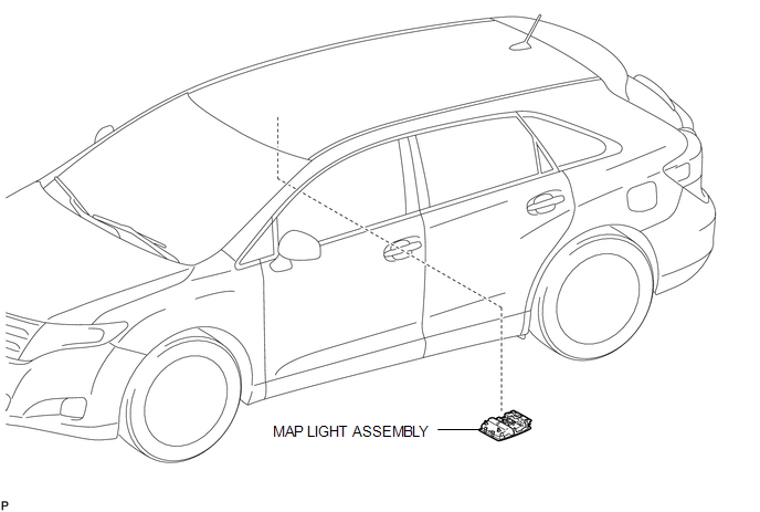
1. REMOVE MAP LIGHT ASSEMBLY
.gif)
Inspection
INSPECTION
PROCEDURE
1. INSPECT SLIDING ROOF SWITCH (ROOF CONSOLE BOX ASSEMBLY)
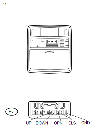
(a) Measure the resistance according to the value(s) in the table below.
Standard Resistance:
|
Tester Connection |
Switch Condition |
Specified Condition |
|---|---|---|
|
P6-4 (DOWN) - P6-1 (GND) |
TILT DOWN switch is pressed |
Below 1 Ω |
|
P6-4 (DOWN) - P6-1 (GND) |
TILT DOWN switch is not pressed |
10 kΩ or higher |
|
P6-5 (UP) - P6-1 (GND) |
TILT UP switch is pressed |
Below 1 Ω |
|
P6-5 (UP) - P6-1 (GND) |
TILT UP switch is not pressed |
10 kΩ or higher |
|
P6-2 (CLS) - P6-1 (GND) |
SLIDE CLOSE switch is pressed |
Below 1 Ω |
|
P6-2 (CLS) - P6-1 (GND) |
SLIDE CLOSE switch is not pressed |
10 kΩ or higher |
|
P6-3 (OPN) - P6-1 (GND) |
SLIDE OPEN switch is pressed |
Below 1 Ω |
|
P6-3 (OPN) - P6-1 (GND) |
SLIDE OPEN switch is not pressed |
10 kΩ or higher |
|
*1 |
Component without harness connected Sliding Roof Switch (Roof Console Box Assembly) |
If the result is not as specified, replace the sliding roof switch (roof console box assembly).
Installation
INSTALLATION
PROCEDURE
1. INSTALL MAP LIGHT ASSEMBLY
.gif)
 Installation
INSTALLATION
PROCEDURE
1. TEMPORARILY INSTALL SLIDING ROOF HOUSING ASSEMBLY
(a) Temporarily install the sliding roof housing panel with the 18 nuts.
NOTICE:
When installing the housing to ...

Other materials about Toyota Venza:
Fog light switch
The fog lights improve visibility in difficult driving conditions, such as
in rain or fog. The fog lights can be used when the headlights are on low beam.
Type A
1. Off
2. On
Type B
1. Off
2. On
Wiper intervals can be adjusted for intermittent ...
Headlight Solenoid Circuit
DESCRIPTION
for HID Headlight:
When the main body ECU receives a high beam turn on signal, the main
body ECU activates the bi-function by controlling the BI-XENON relay. The
bi-function increases the upper illumination area of the discharge ...
Precaution
PRECAUTION
1. PRECAUTION FOR DISCONNECTING CABLE FROM NEGATIVE BATTERY TERMINAL
NOTICE:
When disconnecting the cable from the negative (-) battery terminal, initialize
the following system after the cable is reconnected.
System Name
...

0.1768