Toyota Venza: Satellite Radio Antenna
Components
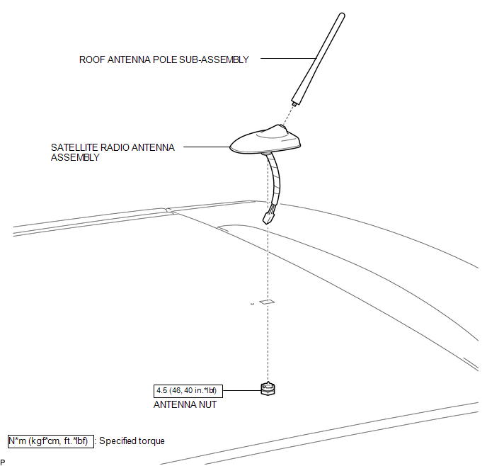
COMPONENTS
ILLUSTRATION
.png)
ILLUSTRATION
Removal
REMOVAL
PROCEDURE
1. REMOVE ROOF HEADLINING ASSEMBLY
(See page .gif) )
)
2. REMOVE ROOF ANTENNA POLE SUB-ASSEMBLY
3. REMOVE SATELLITE RADIO ANTENNA ASSEMBLY
|
(a) Disconnect the connector. |
|
.png)
|
(b) Remove the antenna nut. |
|
.png)
|
(c) Disengage the 2 claws and remove the satellite radio antenna assembly. |
|
.png)
Installation
INSTALLATION
PROCEDURE
1. INSTALL SATELLITE RADIO ANTENNA ASSEMBLY
(a) Engage the 2 claws to the vehicle body to temporarily install the satellite radio antenna assembly.
|
(b) Place the antenna cord in the cutout of the antenna nut. Text in Illustration
|
|
.png)
(c) Install the satellite radio antenna assembly with the antenna nut.
Torque:
4.5 N·m {46 kgf·cm, 40 in·lbf}
(d) Connect the connector.
2. INSTALL ROOF ANTENNA POLE SUB-ASSEMBLY
.gif)
3. INSTALL ROOF HEADLINING ASSEMBLY
(See page )
 Installation
INSTALLATION
PROCEDURE
1. INSTALL REAR NO. 2 SPEAKER ASSEMBLY (for 13 Speakers)
(a) Install the rear No. 2 speaker assembly with the 2 screws.
...

Other materials about Toyota Venza:
How To Proceed With Troubleshooting
CAUTION / NOTICE / HINT
HINT:
Use the following procedure to troubleshoot the start function.
*: Use the Techstream.
PROCEDURE
1.
VEHICLE BROUGHT TO WORKSHOP
NEXT
...
Removal
REMOVAL
PROCEDURE
1. REMOVE FRONT WIPER ARM HEAD CAP
(a) Using a screwdriver, remove the 2 front wiper arm head caps as shown
in the illustration.
Text in Illustration
*1
Protective Tape
...
Voice is not Recognized
PROCEDURE
1.
CHECK CONDITION
(a) Check if the system voice recognition level is low when recognizing a particular
voice.
Result
Proceed to
System voice recognition level is low with an ...

0.1811