Toyota Venza: Removal
REMOVAL
PROCEDURE
1. REMOVE BRAKE BOOSTER ASSEMBLY
HINT:
Refer to the instructions for Removal of the brake booster assembly (See page
.gif) ).
).
2. REMOVE HEADLIGHT LEVELING ECU ASSEMBLY (w/ HID Headlight System)
3. REMOVE STOP LIGHT SWITCH ASSEMBLY
4. REMOVE STOP LIGHT SWITCH MOUNTING ADJUSTER
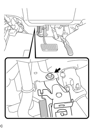
5. REMOVE BRAKE PEDAL SUPPORT ASSEMBLY
|
(a) Disconnect the connector. |
|

|
(b) Remove the bolt and brake pedal support assembly from the instrument panel reinforcement. |
|
 Components
COMPONENTS
ILLUSTRATION
ILLUSTRATION
...
 Disassembly
DISASSEMBLY
PROCEDURE
1. REMOVE BRAKE PEDAL RETURN SPRING
(a) Remove the brake pedal return spring from the brake pedal support
assembly.
...
Other materials about Toyota Venza:
Front Blower Motor
Components
COMPONENTS
ILLUSTRATION
Installation
INSTALLATION
PROCEDURE
1. INSTALL FRONT BLOWER MOTOR SUB-ASSEMBLY
(a) Install the front blower motor sub-assembly with the 3 screws.
(b) Con ...
A/C ECU Vehicle Information Reading/Writing Processor Malfunction (B15F5)
DESCRIPTION
This DTC is stored when items controlled by the air conditioning amplifier assembly
cannot be customized via the navigation system vehicle customization screen.
HINT:
The air conditioning amplifier assembly controls the air conditioning system ...
Security Indicator Light Circuit
DESCRIPTION
The security indicator light blinks continuously due to a continuous signal received
from the transponder key ECU assembly while in the armed state.
WIRING DIAGRAM
CAUTION / NOTICE / HINT
NOTICE:
If the transponder key ECU assembly is repl ...

0.1307