Toyota Venza: Components
COMPONENTS
ILLUSTRATION
ILLUSTRATION
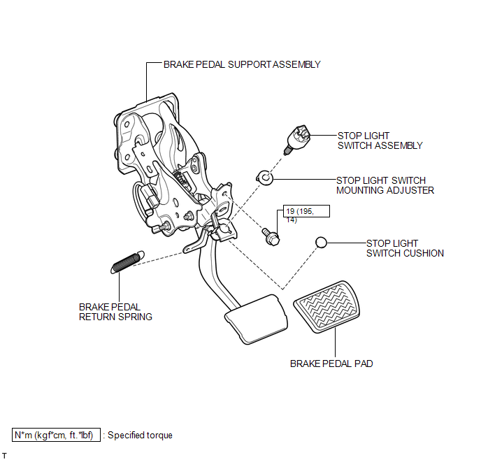
 Brake Pedal
...
 Removal
REMOVAL
PROCEDURE
1. REMOVE BRAKE BOOSTER ASSEMBLY
HINT:
Refer to the instructions for Removal of the brake booster assembly (See page
).
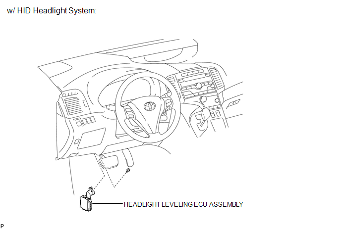
2. REMOVE HEADLIGHT LEVELING ECU ASSEMBLY (w/ HID Headl ...
Other materials about Toyota Venza:
Compressor Solenoid Circuit (B1451/51)
DESCRIPTION
In this circuit, the A/C compressor receives a refrigerant compression demand
signal from the A/C amplifier.
Based on this signal, the A/C compressor changes the amount of compressor output.
DTC No.
DTC Detection Conditio ...
Installation
INSTALLATION
PROCEDURE
1. INSTALL VACUUM SWITCHING VALVE ASSEMBLY (for ACIS)
(a) Install the vacuum switching valve assembly (for ACIS) with the bolt.
Torque:
9.0 N·m {92 kgf·cm, 80 in·lbf}
...
Driver Side Power Mirror cannot be Adjusted with Power Mirror Switch
SYSTEM DESCRIPTION
When the mirror adjust switch is operated, the main body ECU (driver side junction
block assembly) detects the switch operation and sends the mirror adjust switch
signal to the outer mirror control ECU assembly (driver door) via CAN com ...

0.1354