Toyota Venza: Removal
REMOVAL
PROCEDURE
1. REMOVE UPPER CONSOLE PANEL SUB-ASSEMBLY (w/o Seat Heater System)
.gif)
2. REMOVE UPPER CONSOLE PANEL SUB-ASSEMBLY (w/ Seat Heater System)
3. REMOVE NO. 2 CONSOLE BOX CARPET
4. REMOVE CONSOLE BOX ASSEMBLY
5. REMOVE AIR CONDITIONING CONTROL ASSEMBLY
6. REMOVE FRONT DOOR SCUFF PLATE LH
7. REMOVE COWL SIDE TRIM SUB-ASSEMBLY LH
8. REMOVE LOWER NO. 1 INSTRUMENT PANEL FINISH PANEL
9. REMOVE FRONT DOOR SCUFF PLATE RH
10. REMOVE COWL SIDE TRIM SUB-ASSEMBLY RH
11. REMOVE NO. 2 INSTRUMENT PANEL UNDER COVER SUB-ASSEMBLY
12. REMOVE LOWER INSTRUMENT PANEL SUB-ASSEMBLY
13. REMOVE SHIFT LEVER KNOB SUB-ASSEMBLY
14. REMOVE POSITION INDICATOR HOUSING ASSEMBLY
15. REMOVE CONSOLE BOX SUB-ASSEMBLY
16. REMOVE POWER POINT SOCKET ASSEMBLY
|
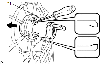
(a) Using a screwdriver, disengage the 2 claws and remove the power point socket assembly as shown in the illustration. Text in Illustration
HINT: Tape the screwdriver tip before use. |
|
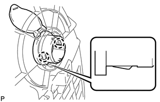
17. REMOVE POWER OUTLET SOCKET COVER NO.1
|
(a) Disengage the 2 claws and remove the power point socket cover. |
|
 Components
COMPONENTS
ILLUSTRATION
ILLUSTRATION
...
 Installation
INSTALLATION
PROCEDURE
1. INSTALL POWER OUTLET SOCKET COVER NO.1
(a) Engage the 2 claws to install the power point socket cover.
2. INSTAL ...
Other materials about Toyota Venza:
Terminals Of Ecu
TERMINALS OF ECU
1. CHECK MAIN BODY ECU (DRIVER SIDE JUNCTION BLOCK ASSEMBLY)
(a) Disconnect the 2A, 2C and 2F main body ECU (driver side junction block assembly)
connectors.
(b) Measure the voltage and resistance according to the value(s) in the table ...
Vehicle Speed Sensor "A" Intermittent / Erratic / High (P0503)
DESCRIPTION
If a malfunction (a rapid change in vehicle speed) in the vehicle speed signal
being output from the skid control ECU is detected while the cruise control is in
operation, the ECM determines that there is a momentary interruption or noise, and ...
Installation
INSTALLATION
PROCEDURE
1. INSTALL ENGINE MOUNTING DAMPER
(a) Install the engine mounting damper with the 3 bolts.
Torque:
9.0 N·m {92 kgf·cm, 80 in·lbf}
2. INSTALL WIRING HARNESS CLAMP BRA ...

0.1343