Toyota Venza: Removal
REMOVAL
PROCEDURE
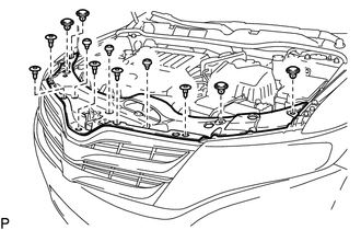
1. REMOVE COOL AIR INTAKE DUCT SEAL
|
(a) Using a clip remover, remove the 12 clips and cool air intake duct seal. |
|
2. REMOVE RADIATOR GRILLE
.gif)
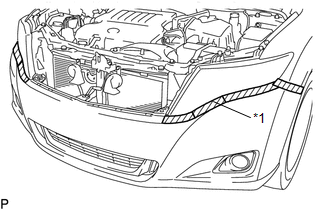
3. REMOVE FRONT BUMPER ASSEMBLY
|
(a) Put protective tape around the front bumper assembly. Text in Illustration
|
|
|
(b) Remove the 2 bolts and 6 screws. |
|
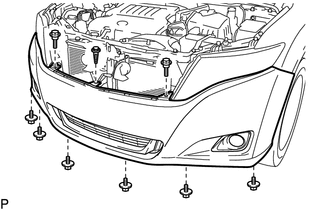
(c) Using a clip remover, remove the clip.
|
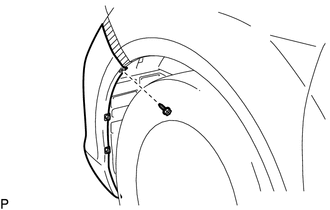
(d) Remove the screw. HINT: Use the same procedure for the RH side and LH side. |
|
|
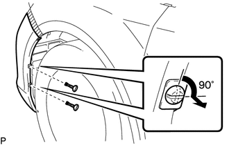
(e) Using a screwdriver, turn the 2 pins 90 degrees and remove the 2 pin hold clips. HINT: Use the same procedure for the RH side and LH side. |
|
|
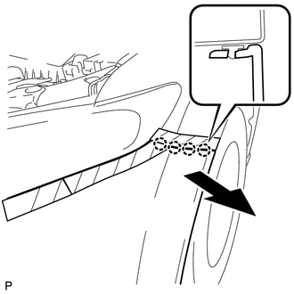
(f) Disengage the 4 claws and remove the front bumper assembly. HINT: Use the same procedure for the RH side and LH side. |
|
(g) Disconnect each connector.
|
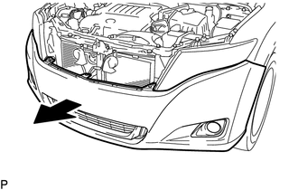
(h) Remove the front bumper assembly as shown in the illustration. |
|
 Components
COMPONENTS
ILLUSTRATION
ILLUSTRATION
ILLUSTRATION
ILLUSTRATION
...
 Disassembly
DISASSEMBLY
PROCEDURE
1. REMOVE NO. 1 ULTRASONIC SENSOR (w/ Intuitive Parking Assist System)
2. REMOVE NO. 2 ULTRASONIC SENSOR RETAINER (w/ Intuitive Parking Assist System)
3. REMOVE FRONT L ...
Other materials about Toyota Venza:
Front Power Seat does not Operate with Front Power Seat Switch
DESCRIPTION
Signals are input into the position control ECU and switch assembly. The built-in
ECU manages the signals received from the position control ECU and switch assembly,
and operates each motor. If the position control ECU and switch assembly rece ...
No Response from Steering Lock ECU (B2786)
DESCRIPTION
This DTC is stored when LIN communication between the certification ECU (smart
key ECU assembly) and steering lock ECU (steering lock actuator assembly) stops
for more than 10 seconds.
DTC No.
DTC Detection Condition
...
Customize Parameters
CUSTOMIZE PARAMETERS
1. CUSTOMIZING FUNCTION WITH TECHSTREAM
HINT:
The following items can be customized.
NOTICE:
When the customer requests a change in a function, first make sure that
the function can be customized.
Be sure to make a not ...

0.1274