Toyota Venza: Removal
REMOVAL
PROCEDURE
1. REMOVE ENGINE OIL LEVEL DIPSTICK GUIDE
|
(a) Remove the engine oil level dipstick. |
|
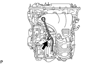
(b) Remove the bolt and engine oil level dipstick guide.
(c) Remove the O-ring from the engine oil level dipstick guide.
2. REMOVE NO. 1 EXHAUST MANIFOLD HEAT INSULATOR
.gif)
3. REMOVE MANIFOLD STAY
4. REMOVE NO. 2 MANIFOLD STAY
5. REMOVE EXHAUST MANIFOLD CONVERTER SUB-ASSEMBLY
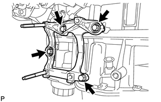
6. REMOVE NO. 1 COMPRESSOR MOUNTING BRACKET
|
(a) Remove the 4 bolts and bracket. |
|
7. REMOVE THROTTLE BODY ASSEMBLY
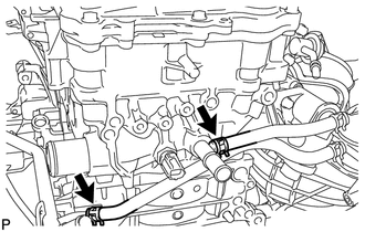
8. REMOVE WATER BY-PASS HOSE
|
(a) Remove the No. 1 and No. 2 water by-pass hoses. |
|
9. DISCONNECT NO. 2 VENTILATION HOSE
10. REMOVE INTAKE MANIFOLD
11. REMOVE SENSOR WIRE
|
(a) Disconnect the knock control sensor connector. |
|
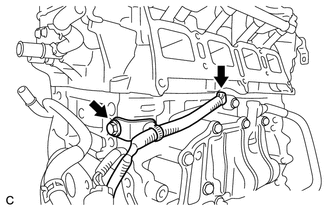
(b) Remove the bolt and sensor wire.
12. REMOVE KNOCK CONTROL SENSOR
13. REMOVE ENGINE OIL PRESSURE SWITCH ASSEMBLY
14. REMOVE ENGINE COOLANT TEMPERATURE SENSOR
15. REMOVE FUEL DELIVERY PIPE SUB-ASSEMBLY
16. REMOVE IGNITION COIL ASSEMBLY
 Components
COMPONENTS
ILLUSTRATION
ILLUSTRATION
ILLUSTRATION
ILLUSTRATION
ILLUSTRATION
ILLUSTRATION
ILLUSTRATION
ILLUSTRATION
ILLUSTRATION
ILLUSTRATION
...
 Disassembly
DISASSEMBLY
PROCEDURE
1. REMOVE ENGINE COVER JOINT
(a) Remove the 3 joints.
2. REMOVE SPARK PLUG
3. REMOVE CAMSHAFT TIMING OIL CONTROL ...
Other materials about Toyota Venza:
Radio Antenna Pole
Components
COMPONENTS
ILLUSTRATION
Removal
REMOVAL
PROCEDURE
1. REMOVE ROOF ANTENNA POLE SUB-ASSEMBLY
(a) Turn the roof antenna pole sub-assembly in the direction indicated
by the arrow in the illustration to remove it.
...
Removal
REMOVAL
CAUTION / NOTICE / HINT
HINT:
Use the same procedure for the LH side and RH side.
The following procedure listed below is for the LH side.
PROCEDURE
1. REMOVE FRONT WHEEL
2. REMOVE FRONT WIPER ARM HEAD CAP
3. REMOVE FRONT WI ...
Sound Quality is Bad Only when CD is Played (Volume is Too Low)
PROCEDURE
1.
REPLACE CD AND RECHECK
(a) Replace the CD with a new or known good one and check that the malfunction
disappears.
OK:
Malfunction disappears.
OK
END
NG
REPLACE ...

0.1717