
Toyota Venza: Rear Occupant Classification Sensor LH Collision Detection (B1787)
DESCRIPTION
DTC B1787 is output when the occupant classification ECU receives a collision detection signal sent by the rear occupant classification sensor LH if an accident occurs.
DTC B1787 is also output when the front seat assembly RH is subjected to a strong impact, even if an actual accident does not occur.
However, when the occupant classification ECU outputs a collision detection signal, even if the vehicle is not in a collision, DTC B1787 can be cleared by Zero Point Calibration and Sensitivity Check.
Therefore, if DTC B1787 is output, first perform Zero Point Calibration and Sensitivity Check.
|
DTC No. |
DTC Detection Condition |
Trouble Area |
|---|---|---|
|
B1787 |
|
|
HINT:
When DTC B1650/32 is detected as a result of troubleshooting for the airbag system, check the DTCs stored in the occupant classification ECU. When DTC B1787 is output, perform troubleshooting for the DTC.
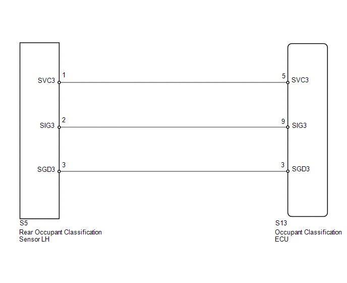
WIRING DIAGRAM
PROCEDURE
|
1. |
PERFORM ZERO POINT CALIBRATION |
(a) Connect the Techstream to the DLC3.
(b) Turn the ignition switch to ON.
(c) Using the Techstream, perform Zero Point Calibration (See page
.gif) ).
).
OK:
"Zero Point Calibration is complete." is displayed.
| NG | .gif) |
GO TO STEP 4 |
|
.gif)
|
2. |
PERFORM SENSITIVITY CHECK |
(a) Using the Techstream, perform Sensitivity Check (See page
).
Standard:
27 to 33 kg (59.5 to 72.8 lb)
| NG | |
GO TO STEP 4 |
|
|
3. |
CHECK DTC |
(a) Turn the ignition switch to ON.
(b) Clear the DTCs stored in the occupant classification ECU (See page
).
(c) Clear the DTCs stored in the center airbag sensor assembly (See page
).
(d) Turn the ignition switch off.
(e) Turn the ignition switch to ON.
(f) Check for DTCs (See page ).
OK:
DTC B1787 is not output.
HINT:
Codes other than DTC B1787 may be output at this time, but they are not related to this check.
| OK | |
END |
|
|
4. |
REPLACE FRONT SEAT FRAME WITH ADJUSTER ASSEMBLY RH |
(a) Turn the ignition switch off.
(b) Disconnect the cable from the negative (-) battery terminal.
(c) Replace the front seat frame with adjuster assembly RH (See page
for power seat or
for manual seat).
HINT:
Perform the inspection using parts from a normal vehicle if possible.
|
|
5. |
PERFORM ZERO POINT CALIBRATION |
(a) Connect the cable to the negative (-) battery terminal.
(b) Connect the Techstream to the DLC3.
(c) Turn the ignition switch to ON.
(d) Using the Techstream, perform Zero Point Calibration (See page
).
OK:
"Zero Point Calibration is complete." is displayed.
| NG | |
GO TO STEP 8 |
|
|
6. |
PERFORM SENSITIVITY CHECK |
(a) Using the Techstream, perform Sensitivity Check (See page
).
Standard:
27 to 33 kg (59.5 to 72.8 lb)
| NG | |
GO TO STEP 8 |
|
|
7. |
CHECK DTC |
(a) Turn the ignition switch to ON.
(b) Clear the DTCs stored in the occupant classification ECU (See page
).
(c) Clear the DTCs stored in the center airbag sensor assembly (See page
).
(d) Turn the ignition switch off.
(e) Turn the ignition switch to ON.
(f) Check for DTCs (See page ).
OK:
DTC B1787 is not output.
HINT:
Codes other than DTC B1787 may be output at this time, but they are not related to this check.
| OK | |
END |
|
|
8. |
REPLACE OCCUPANT CLASSIFICATION ECU |
(a) Turn the ignition switch off.
(b) Disconnect the cable from the negative (-) battery terminal.
(c) Replace the occupant classification ECU (See page
).
|
|
9. |
PERFORM ZERO POINT CALIBRATION |
(a) Connect the cable to the negative (-) battery terminal.
(b) Connect the Techstream to the DLC3.
(c) Turn the ignition switch to ON.
(d) Using the Techstream, perform Zero Point Calibration (See page
).
OK:
"Zero Point Calibration is complete." is displayed.
|
|
10. |
PERFORM SENSITIVITY CHECK |
(a) Using the Techstream, perform Sensitivity Check (See page
).
Standard:
27 to 33 kg (59.5 to 72.8 lb)
| NEXT | |
END |
 Center Airbag Sensor Assembly Communication Circuit Malfunction (B1790)
DESCRIPTION
The center airbag sensor assembly communication circuit consists of the occupant
classification ECU and center airbag sensor assembly.
DTC B1790 is recorded when a malfunction is detec ...
 Rear Occupant Classification Sensor RH Collision Detection (B1788)
DESCRIPTION
DTC B1788 is output when the occupant classification ECU receives a collision
detection signal sent by the rear occupant classification sensor RH if an accident
occurs.
DTC B1788 is ...
Other materials about Toyota Venza:
ECM Communication Stop Mode
DESCRIPTION
Detection Item
Symptom
Trouble Area
ECM Communication Stop Mode
"Engine" and "ECT" are not displayed on "CAN Bus Check" screen
of the Techs ...
MIL Circuit
DESCRIPTION
The MIL (Malfunction Indicator Lamp) is used to indicate vehicle malfunctions
detected by the ECM. By turning the ignition switch to ON, power is supplied to
the MIL circuit, and the ECM provides the circuit ground which illuminates the MIL.
...
Fail-safe Chart
FAIL-SAFE CHART
1. FAIL-SAFE FUNCTION
(a) When communication fails in any of the CAN bus wires (communication wires),
a fail-safe function(s) will operate. The fail-safe function that is specified for
each system operates to prevent those systems from ma ...

0.134