Toyota Venza: Installation
INSTALLATION
PROCEDURE
1. INSTALL FRONT BUMPER ASSEMBLY
(a) Connect each connector.
|
(b) Engage the 4 claws to install the front bumper assembly. HINT: Use the same procedure for the RH side and LH side. |
|
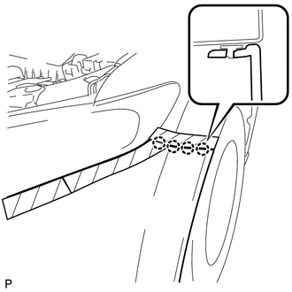
(c) Install the clip.
(d) Install the 2 bolts and 8 screws.
|
(e) Install the 2 pin hold clips. Text in Illustration
NOTICE: Insert the pin hold clip with the slot aligned vertically. Do not rotate the clip after inserting it. After installation, confirm that the slot is vertical. HINT: Use the same procedure for the RH side and LH side. |
|
2. INSTALL RADIATOR GRILLE
.gif)
3. INSTALL COOL AIR INTAKE DUCT SEAL
(a) Install the cool air intake duct seal with the 12 clips.
4. ADJUST FOG LIGHT ASSEMBLY
(See page )
 Reassembly
REASSEMBLY
PROCEDURE
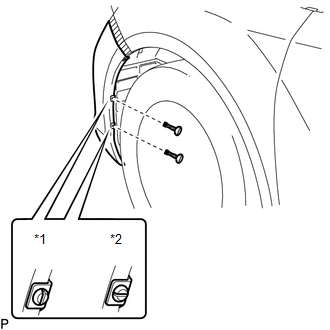
1. INSTALL FRONT BUMPER SIDE RETAINER LH
(a) Engage the claw and install the front bumper side retainer LH.
Text in Illustration
*1
...

Other materials about Toyota Venza:
Reassembly
REASSEMBLY
PROCEDURE
1. INSTALL TRANSFER DRIVEN PINION REAR BEARING
(a) Using SST and a press, press the transfer driven pinion rear bearing
(outer race) to the case.
SST: 09950-60010
09951-00620
SST: 09950-70010
09951-07150
NO ...
Engine Hood Courtesy Switch
Components
COMPONENTS
ILLUSTRATION
Inspection
INSPECTION
PROCEDURE
1. INSPECT SECURITY COURTESY SWITCH (HOOD LOCK ASSEMBLY)
(a) Measure the resistance according to the value(s) in the table below.
Standard Resistance:
...
Front Occupant Classification Sensor RH Circuit Malfunction (B1781)
DESCRIPTION
The front occupant classification sensor RH circuit consists of the occupant
classification ECU and front occupant classification sensor RH.
DTC B1781 is recorded when a malfunction is detected in the front occupant classification
sensor RH c ...

0.1496