Toyota Venza: Precaution
PRECAUTION
1. PRECAUTION FOR VEHICLE WITH SRS AIRBAG AND SEAT BELT PRETENSIONER
(a) Some operations in this section may affect the SRS airbags. Prior to performing
the corresponding operations, read the precautions regarding the SRS airbags (See
page .gif) ).
).
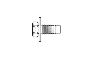
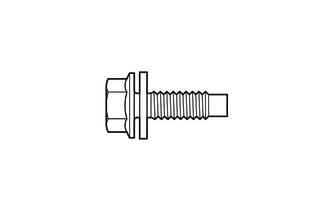
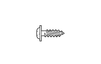
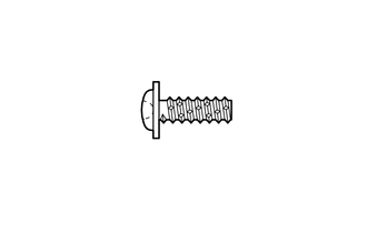
2. TABLE OF BOLT, SCREW AND NUT
HINT:
All bolts, screws and nuts relevant to installing and removing the instrument panel are shown along with their alphabet code in the table below.
|
Code |
Shape |
Size |
Code |
Shape |
Size |
|---|---|---|---|---|---|
|
<A> |
 |
φ = 8 mm (0.315 in.) Length = 20 mm (0.787 in.) |
<B> |
 |
φ = 8 mm (0.315 in.) Length = 25 mm (0.984 in.) |
|
<C> |
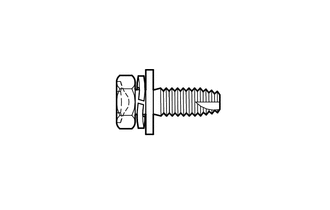 |
φ = 6 mm (0.236 in.) Length = 18 mm (0.709 in.) |
<D> |
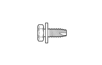 |
φ = 6 mm (0.236 in.) Length = 15 mm (0.591 in.) |
|
<E> |
 |
φ = 5 mm (0.197 in.) Length = 16 mm (0.630 in.) |
<F> |
 |
φ = 5 mm (0.197 in.) Length = 14 mm (0.551 in.) |
|
<G> |
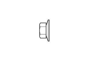 |
φ = 6 mm (0.236 in.) |
<H> |
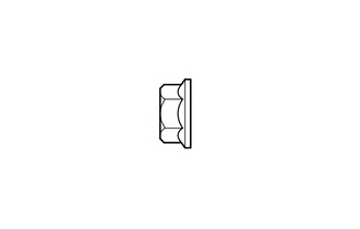 |
φ = 6 mm (0.236 in.) |

 Components
COMPONENTS
ILLUSTRATION
ILLUSTRATION
ILLUSTRATION
ILLUSTRATION
ILLUSTRATION
ILLUSTRATION
ILLUSTRATION
ILLUSTRATION
ILLUSTRATION
ILLUSTRATION
...
Other materials about Toyota Venza:
How To Use This Manual
General Information
GENERAL INFORMATION
1. GENERAL DESCRIPTION
(a) This manual is written in accordance with SAE J2008.
(b) Repair operations can be separated mainly into the following 3 processes:
(1) Diagnosis
(2) Removing / Installing, Replacing, Di ...
Garage Door Opener Switch
Components
COMPONENTS
ILLUSTRATION
Removal
REMOVAL
PROCEDURE
1. REMOVE ROOF CONSOLE BOX ASSEMBLY (GARAGE DOOR OPENER SWITCH)
(a) Using a moulding remover, disengage the 2 claws and 2 clips.
Text in Illustration
*1 ...
Capacity and distribution
Cargo capacity depends on the total weight of the occupants.
(Cargo capacity) = (Total load capacity) — (Total weight of occupants) Steps
for Determining Correct Load Limit—
(1) Locate the statement “The combined weight of occupants and cargo should ...

0.1937