Toyota Venza: Parts Location
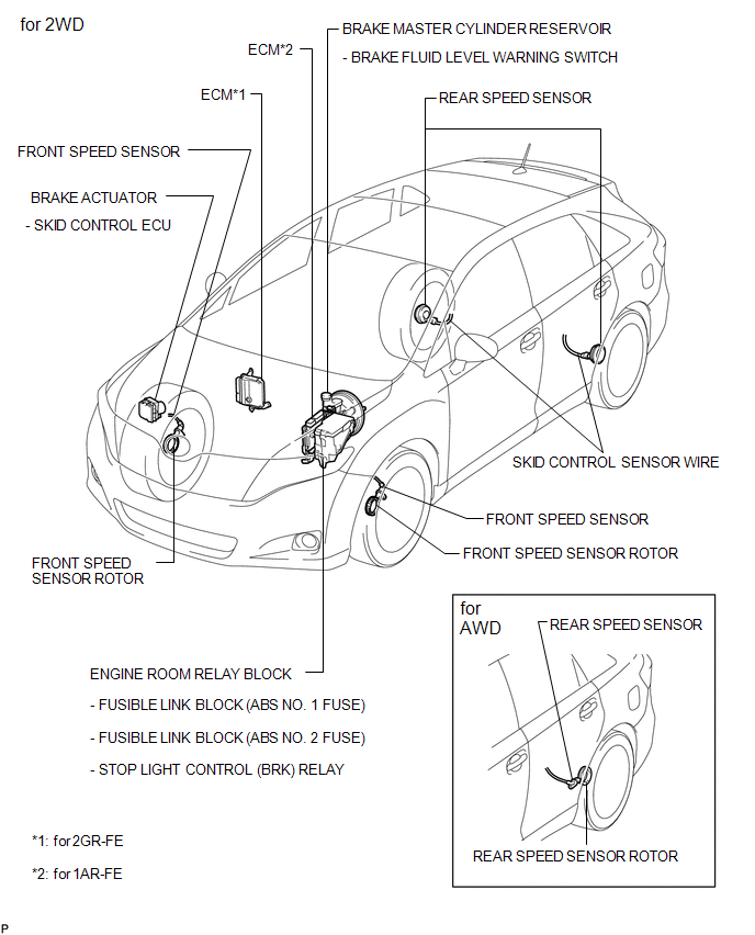
PARTS LOCATION
ILLUSTRATION
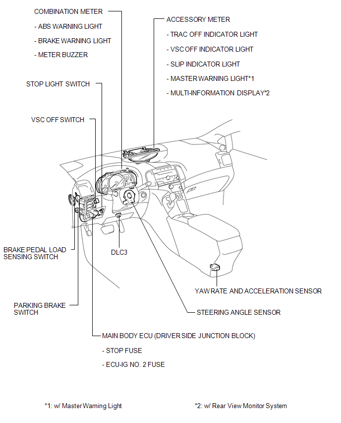
ILLUSTRATION
 Precaution
PRECAUTION
1. PRECAUTION FOR DISCONNECTING THE BATTERY CABLE
NOTICE:
When disconnecting the cable from the negative (-) battery terminal, initialize
the following systems after the cable is recon ...
 System Description
SYSTEM DESCRIPTION
1. FUNCTION DESCRIPTION
(a) Steering Cooperative Control
(1) Enhanced-VSC performs coordinated control consisting of VSC and electronic
power steering. By integrating these pre ...
Other materials about Toyota Venza:
Disassembly
DISASSEMBLY
PROCEDURE
1. REMOVE TRANSFER AND TRANSAXLE SETTING STUD BOLT
(a) Remove the 4 transfer and transaxle setting stud bolts.
2. REMOVE NO. 2 TRANSFER CASE PLUG
(a) Remove the No. ...
Stop Light Switch
Components
COMPONENTS
ILLUSTRATION
Removal
REMOVAL
PROCEDURE
1. REMOVE STOP LIGHT SWITCH ASSEMBLY
(a) Disconnect the connector.
(b) Turn the stop light switch assembly countercl ...
Engine Hood Courtesy Switch Circuit
DESCRIPTION
The security courtesy switch is installed together with the hood lock. This switch
turns off when the engine hood is opened and turns on when the engine hood is closed.
WIRING DIAGRAM
PROCEDURE
1.
INSPECT HOOD LOCK AS ...

0.1608