Toyota Venza: Parts Location
Toyota Venza Service Manual / Park Assist / Monitoring / Intuitive Parking Assist System / Parts Location
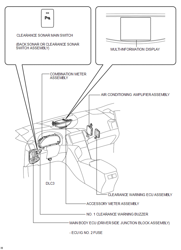
PARTS LOCATION
ILLUSTRATION
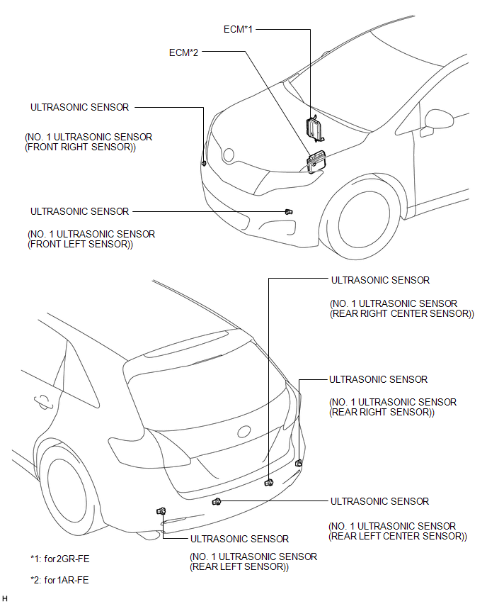
ILLUSTRATION
 Precaution
PRECAUTION
1. PRECAUTION FOR DISCONNECTING CABLE FROM NEGATIVE BATTERY TERMINAL
NOTICE:
When disconnecting the cable from the negative (-) battery terminal, initialize
the following system(s) aft ...
 System Description
SYSTEM DESCRIPTION
1. GENERAL
(a) This system uses ultrasonic sensors to detect any obstacles at the corners
and the rear of the vehicle. The system then informs the driver of the distance
betwe ...
Other materials about Toyota Venza:
Installation
INSTALLATION
PROCEDURE
1. INSTALL REAR BUMPER ASSEMBLY
(a) w/ Intuitive Parking Assist System:
(1) Connect each connector.
(b) Engage the 6 claws and install the rear bumper assembly as shown
in the illustration.
...
Head restraints
Head restraints are provided for all seats.
► Front and rear outboard seats
Vertical adjustment 1. Up
Pull the head restraint up.
2. Down
Push the head restraints down while pressing the lock release button.
► Rear center seat (fabric seat) ...
Components
COMPONENTS
ILLUSTRATION
ILLUSTRATION
ILLUSTRATION
ILLUSTRATION
ILLUSTRATION
...
© 2016-2026 Copyright www.tovenza.com

0.1222
0.1222