Toyota Venza: Parts Location
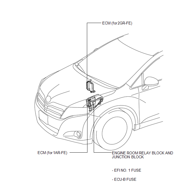
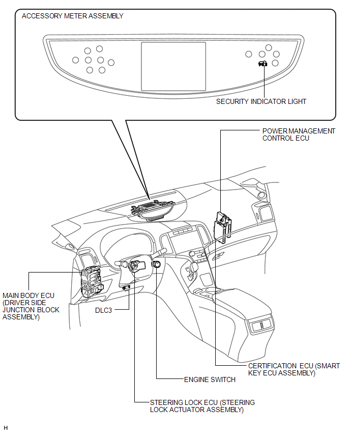
PARTS LOCATION
ILLUSTRATION
ILLUSTRATION

 Precaution
PRECAUTION
1. PRECAUTION FOR DISCONNECTING CABLE FROM NEGATIVE BATTERY TERMINAL
NOTICE:
When disconnecting the cable from the negative (-) battery terminal, initialize
the following system after ...
Other materials about Toyota Venza:
Dtc Check / Clear
DTC CHECK / CLEAR
1. CHECK DTC
(a) Connect the Techstream to the DLC3.
(b) Turn the ignition switch to ON and turn the Techstream on.
(c) Enter the following menus: Body Electrical / Trouble Codes.
(d) Check for DTCs.
2. CLEAR DTC
(a) Connect the Techst ...
Removal
REMOVAL
CAUTION / NOTICE / HINT
HINT:
The front side fix window assembly can be reused. When installing the
window, if any of the clips on the quarter window glass are broken, butyl
tape can be used to support the glass until the applied adh ...
Disassembly
DISASSEMBLY
PROCEDURE
1. REMOVE NO. 1 CONSOLE BOX CARPET
(a) Remove the No. 1 console box carpet.
2. REMOVE INSTRUMENT PANEL CUP HOLDER DAMPER
(a) Pull the instrument panel cup holder da ...

0.1756