Toyota Venza: Parts Location
PARTS LOCATION
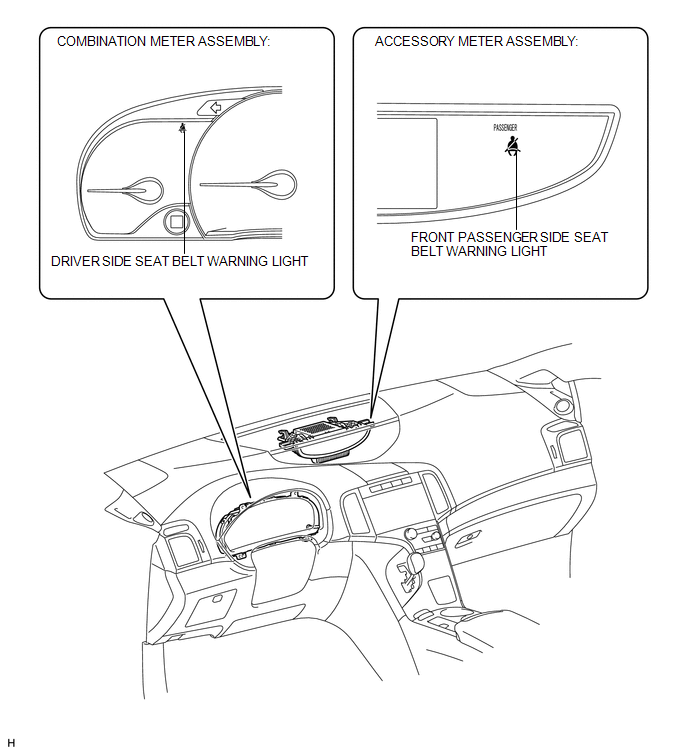
ILLUSTRATION
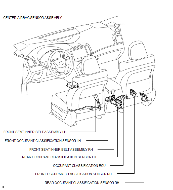
ILLUSTRATION
 Precaution
PRECAUTION
NOTICE:
When disconnecting the cable from the negative (-) battery terminal, initialize
the following systems after the cable is reconnected.
System Name
See Proc ...
 System Description
SYSTEM DESCRIPTION
1. SEAT BELT WARNING SYSTEM DESCRIPTION
If a seat belt is not fastened, this system flashes the seat belt warning light
or sounds the seat belt warning buzzer as a reminder.
(a ...
Other materials about Toyota Venza:
On-vehicle Inspection
ON-VEHICLE INSPECTION
CAUTION / NOTICE / HINT
HINT:
Use the same procedure for the RH side and LH side.
The procedure listed below is for the LH side.
PROCEDURE
1. REMOVE FRONT WHEEL
2. SEPARATE FRONT DISC BRAKE CALIPER ASSEMBLY
3. ...
Freeze Frame Data
FREEZE FRAME DATA
1. FREEZE FRAME DATA
(a) Whenever an ABS DTC is detected, the skid control ECU stores the current
vehicle (sensor) state as Freeze Frame Data.
(b) The skid control ECU stores the number of times (maximum: 31) the ignition
switch has be ...
Diagnosis System
DIAGNOSIS SYSTEM
1. DESCRIPTION
(a) The certification ECU (smart key ECU assembly) control the vehicle smart
key system functions. Smart key system data and Diagnostic Trouble Codes (DTCs)
can be read through the vehicle Data Link Connector 3 (DLC3). In ...

0.1565