Toyota Venza: Parts Location
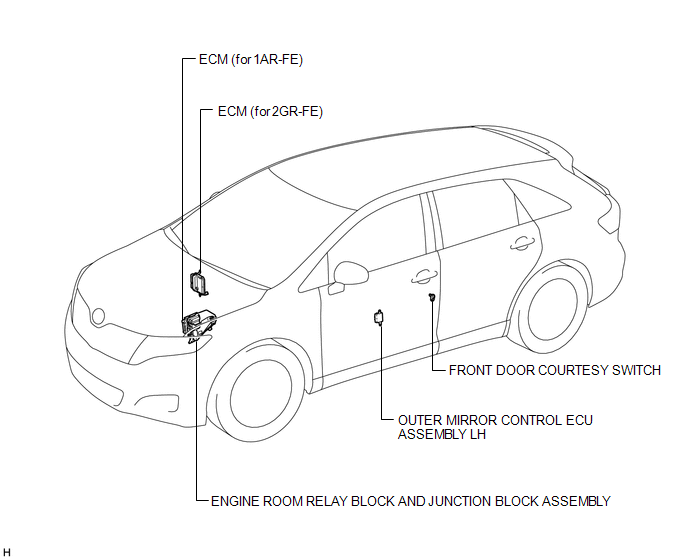
PARTS LOCATION
ILLUSTRATION
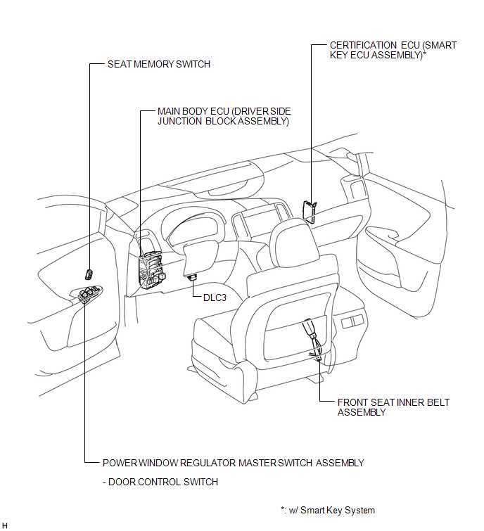
ILLUSTRATION
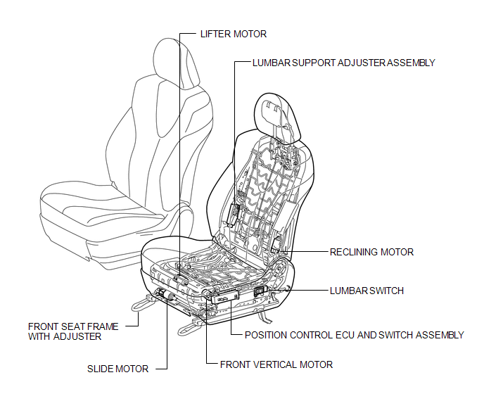
ILLUSTRATION

 Precaution
PRECAUTION
1. PRECAUTION FOR DISCONNECTING CABLE FROM NEGATIVE BATTERY TERMINAL
NOTICE:
When disconnecting the cable from the negative (-) battery terminal, initialize
the following system after ...
Other materials about Toyota Venza:
If you have a flat tire
Remove the flat tire and replace it with the spare provided. - Before
jacking up the vehicle
• Stop the vehicle on a hard, flat surface.
• Set the parking brake.
• Shift the shift lever to “P”.
• Stop the engine.
• Turn on the emergency f ...
XM Tuner Antenna Disconnected (B15FE,B15FF)
DESCRIPTION
These DTCs are stored when a malfunction occurs in the roof antenna assembly
which is connected to the stereo component tuner assembly.
DTC No.
DTC Detection Condition
Trouble Area
B15FE
...
Removal
REMOVAL
CAUTION / NOTICE / HINT
HINT:
Use the same procedure for the RH side and LH side.
The procedure listed below is for the LH side.
PROCEDURE
1. REMOVE FRONT WHEEL
2. REMOVE FRONT AXLE SHAFT NUT
3. SEPARATE FRONT SPEED SENSOR
...

0.131