Toyota Venza: Parts Location
PARTS LOCATION
ILLUSTRATION
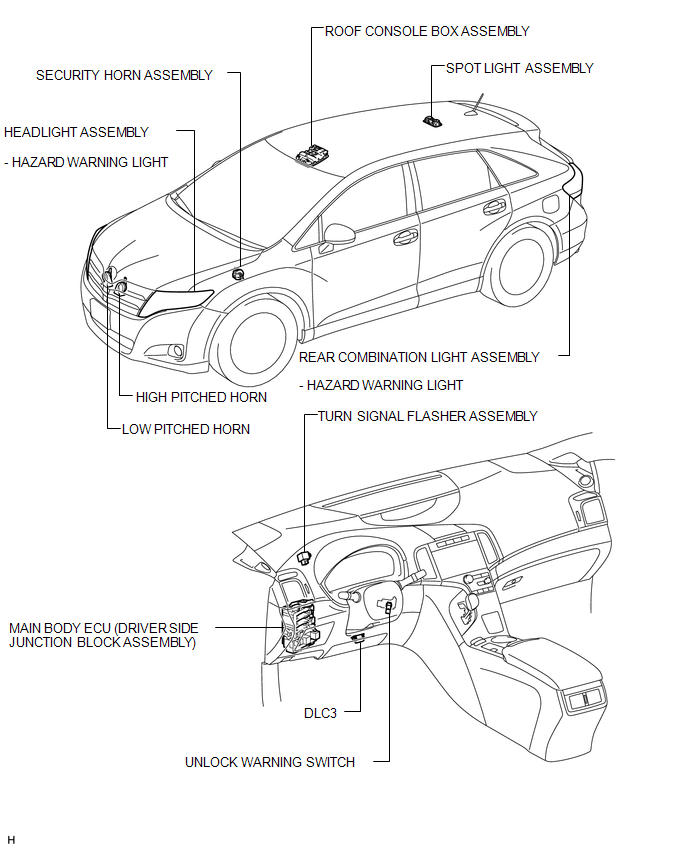
ILLUSTRATION
.png)
 Precaution
PRECAUTION
1. PRECAUTION FOR DISCONNECTING THE BATTERY CABLE
NOTICE:
When disconnecting the cable from the negative (-) battery terminal, initialize
the following systems after the terminal is re ...
 System Description
SYSTEM DESCRIPTION
1. WIRELESS DOOR LOCK CONTROL SYSTEM
The wireless door lock control system functions to lock and unlock all the doors
from a distance. The system is controlled by a door control ...
Other materials about Toyota Venza:
Headlight Solenoid Circuit
DESCRIPTION
for HID Headlight:
When the main body ECU receives a high beam turn on signal, the main
body ECU activates the bi-function by controlling the BI-XENON relay. The
bi-function increases the upper illumination area of the discharge ...
Push Switch / Key Unlock Warning Switch Malfunction (B2780)
DESCRIPTION
This DTC is stored if the transponder key ECU assembly does not detect that the
unlock warning switch assembly is ON even when the ignition switch is ON. Under
normal conditions, the unlock warning switch assembly is ON when the ignition switc ...
How To Proceed With Troubleshooting
CAUTION / NOTICE / HINT
HINT:
Use the following procedure to troubleshoot the wiper and washer system.
PROCEDURE
1.
VEHICLE BROUGHT TO WORKSHOP
NEXT
...

0.1459