Toyota Venza: Parts Location
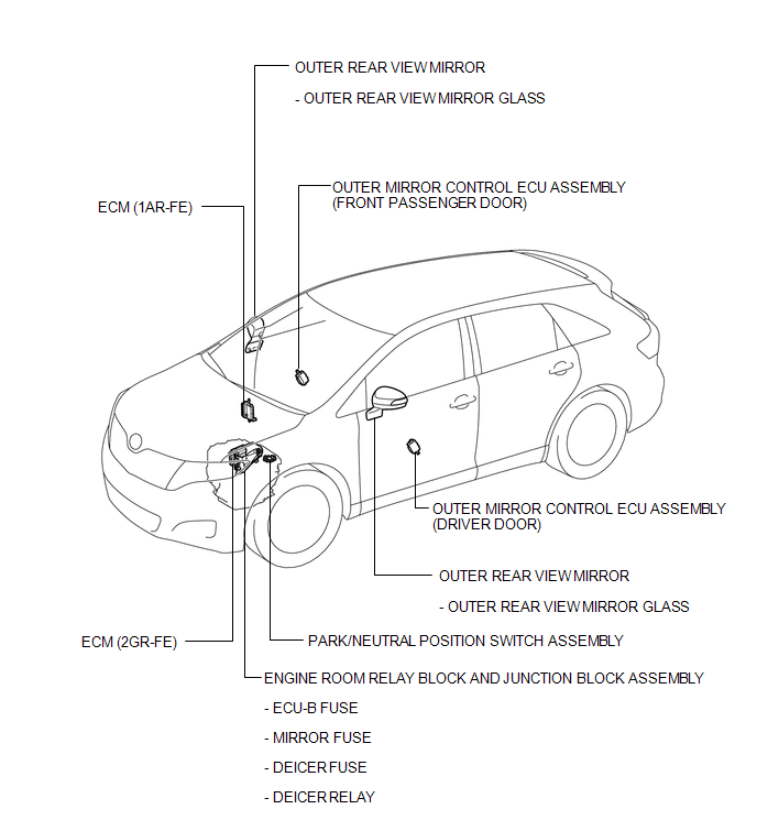
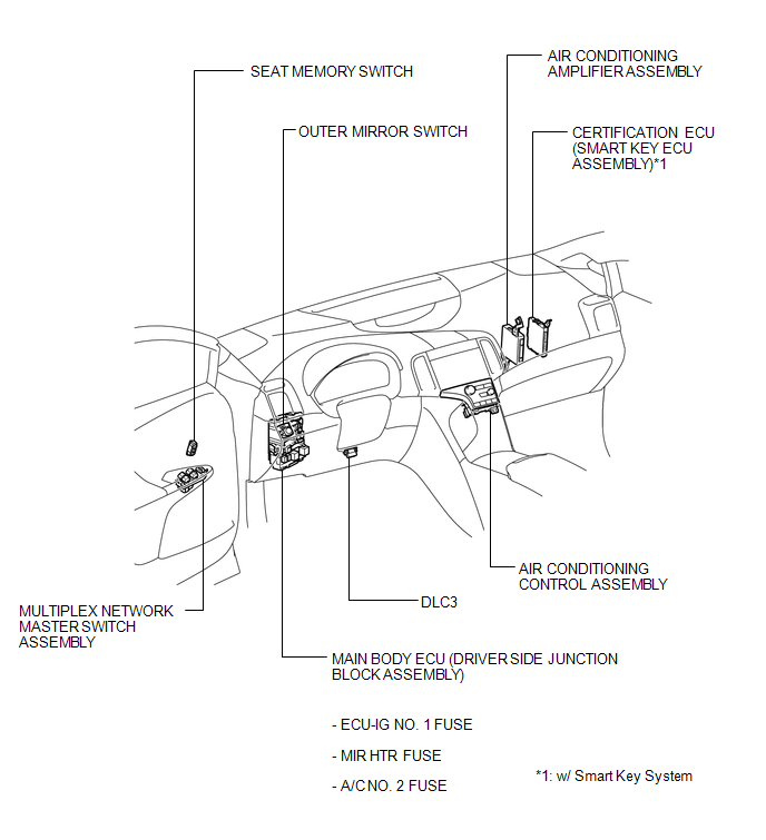
PARTS LOCATION
ILLUSTRATION
ILLUSTRATION
 Precaution
PRECAUTION
1. PRECAUTION FOR DISCONNECTING CABLE FROM NEGATIVE BATTERY TERMINAL
NOTICE:
When disconnecting the cable from the negative (-) battery terminal, initialize
the following system after ...
 System Description
SYSTEM DESCRIPTION
1. POWER MIRROR CONTROL SYSTEM DESCRIPTION
(a) This system has the following functions: power retract mirror function*,
reverse shift-linked function, electrical remote control ...
Other materials about Toyota Venza:
Data List / Active Test
DATA LIST / ACTIVE TEST
1. DATA LIST
HINT:
Using the Techstream to read the Data List allows the values or states of switches,
sensors, actuators and other items to be read without removing any parts. This non-intrusive
inspection can be very useful bec ...
Disposal
DISPOSAL
PROCEDURE
1. DISPOSE OF FRONT SHOCK ABSORBER ASSEMBLY
(a) Position the front shock absorber assembly level with the piston
rod fully extended. Using a drill, make a hole in the cylinder between A
and B as shown in the illustratio ...
Evaporative Emission System Leak Detection Reference Orifice Low Flow (P043E,P043F,P2401,P2402,P2419)
DTC SUMMARY
DTC No.
Monitoring Item
Malfunction Detection Condition
Trouble Area
Detection Timing
Detection Logic
P043E
Reference orifice clogged
P043E, P ...

0.1376