Toyota Venza: Parts Location
PARTS LOCATION
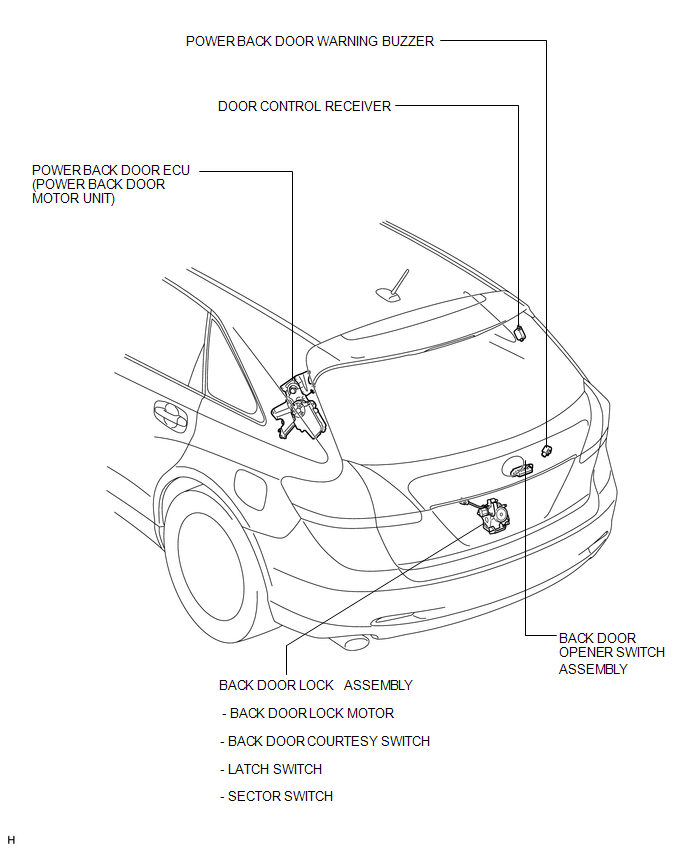
ILLUSTRATION
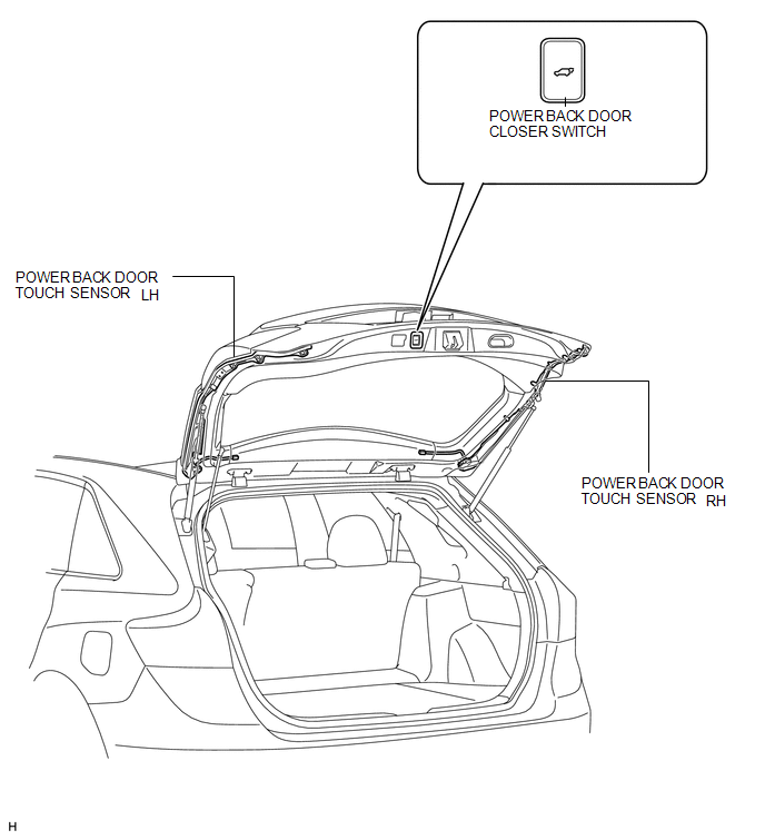
ILLUSTRATION
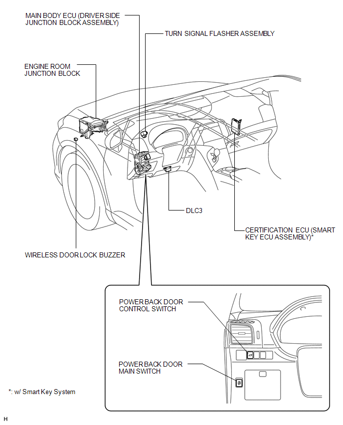
ILLUSTRATION

 Precaution
PRECAUTION
NOTICE:
When disconnecting the cable from the negative (-) battery terminal, initialize
the following system after the cable is reconnected.
System Name
See Proce ...
Other materials about Toyota Venza:
IG Power Supply Voltage Malfunction (C1551)
DESCRIPTION
The power steering ECU distinguishes the ignition switch status as ON or off
through the IG power source circuit.
DTC No.
DTC Detection Condition
Trouble Area
C1551
IG power source ci ...
Speed Sensor(when Not Using The Engine Support Bridge)
Components
COMPONENTS
ILLUSTRATION
Removal
REMOVAL
PROCEDURE
1. REMOVE AUTOMATIC TRANSAXLE ASSEMBLY
HINT:
See the steps from "Remove Engine Assembly with transaxle" through "Remove Automatic
Transaxle Assembly" (See page ). ...
Removal
REMOVAL
PROCEDURE
1. PRECAUTION
CAUTION:
Be sure to read Precaution thoroughly before servicing (See page
).
2. DISCONNECT CABLE FROM NEGATIVE BATTERY TERMINAL
CAUTION:
Wait at least 90 seconds after disconnecting the cable from the negative (-)
bat ...

0.1305