Toyota Venza: Operation Check
OPERATION CHECK
1. CHECK REMOTE CONTROL MIRROR FUNCTION
(a) Turn the ignition switch ON.
(b) With the mirror select switch set to L, check that the outer rear view mirror LH surface moves up, down, left and right normally.
(c) With the mirror select switch set to R, check that the outer rear view mirror RH surface moves up, down, left and right normally.
2. CHECK MEMORY AND REACTIVATION FUNCTION
HINT:
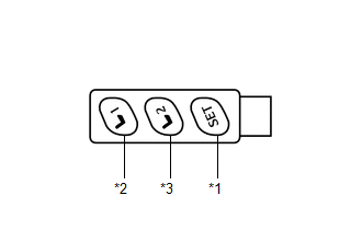
The SET, M1 and M2 seat memory switches are shown in the illustration.
(a) Turn the ignition switch ON and move the shift lever to P.
Text in Illustration|
*1 |
SET Switch |
|
*2 |
M1 Switch |
|
*3 |
M2 Switch |
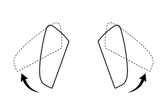
(b) Check the M1 switch.
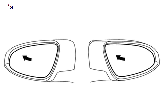
(1) Using the mirror adjust switch, turn the mirror surface to the full left position.
Text in Illustration|
*a |
Turn to Left Fully |
(2) Check that the buzzer sounds for 0.5 seconds and the seat position is memorized when the M1 switch is pressed within 3 seconds of the SET switch being pressed.
NOTICE:
- The mirror surface position will be stored when the M1 switch is pressed after first pressing and holding the SET switch.
- The mirror surface position will not be stored when the SET switch and M1 switch are pressed simultaneously.
- The mirror surface position will not be stored when 2 or more of the memory switches are pressed simultaneously (for example, M1 and M2) after first pressing the SET switch.
(3) Using the outer mirror switch assembly, turn the mirror surface to the full right position.
(4) Press the M1 switch.
(5) Check that the buzzer sounds for 0.1 seconds and the outer mirror automatically moves to the recorded full left position.
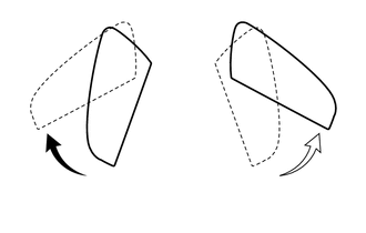
(c) Check the M2 switch.
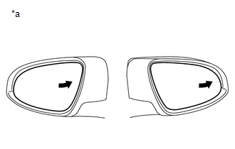
(1) Using the mirror adjust switch assembly, turn the mirror surface to the full right position.
Text in Illustration|
*a |
Turn to Right Fully |
(2) Check that the buzzer sounds for 0.5 seconds and the seat position is memorized when the M2 switch is pressed within 3 seconds of the SET switch being pressed.
NOTICE:
- The mirror surface position will be stored when the M2 switch is pressed after first pressing and holding the SET switch.
- The mirror surface position will not be stored when the SET switch and M2 switch are pressed simultaneously.
- The mirror surface position will not be stored when 2 or more of the memory switches are pressed simultaneously (for example, M1 and M2) after first pressing the SET switch.
(3) Using the outer mirror switch assembly, turn the mirror surface to the full left position.
(4) Press the M2 switch.
(5) Check that the buzzer sounds for 0.1 seconds and the outer mirror automatically moves to the recorded full right position.
3. CHECK POWER RETRACTABLE MIRROR FUNCTION (w/ Retract Mirror)
(a) Turn the ignition switch ON.
(b) At each outer rear view mirror assembly position, check the retractable mirror operation when operating the retractable outer mirror switch.
(1) Move the mirrors to the driving position.
(2) Turn the retractable outer mirror switch to the retract position.
(3) Check that the right and left outer rear view mirror assemblies move from the driving position to the retracted position.
(4) Move the mirrors to the driving position.
(5) Move one of the outer rear view mirror assemblies to the forward position by hand.
(6) Turn the retractable outer mirror switch to the retract position.
(7) Check that the outer rear view mirror assembly in the forward position moves to the retracted position, and check that the other mirror moves to the retracted position.
(8) Move the outer rear view mirror assemblies to the driving position.
(9) Move one of the outer rear view mirror assemblies to the retracted position by hand.
(10) Turn the retractable outer mirror switch to the retract position.
(11) Check that the outer rear view mirror assembly in the driving position moves to the retracted position.
(12) Move the mirrors to the retracted position.
(13) Turn the retractable outer mirror switch to the driving position.
(14) Check that the right and left mirrors move from the retracted position to the driving position.
(15) Move the mirrors to the retracted position.
(16) Move one of the outer rear view mirror assemblies to the driving position by hand.
(17) Turn the retractable outer mirror switch to the driving position.
(18) Check that the retracted outer rear view mirror assembly moves to the driving position.
(c) Check the operation of the outer rear view mirror assembly according to retractable outer mirror switch operations and ignition switch condition.
(1) When the outer rear view mirror assembly is operating, turn the ignition switch off and check that the mirror operation stops immediately.
(2) This time, turn the ignition switch ACC and press the retractable outer mirror switch. Check that the outer rear view mirror assembly operates in the opposite direction.
(d) Check the operation of the outer rear view mirror assembly when it is blocked by an obstacle.
(1) When the outer rear view mirror assembly is moving to the retracted or driving position, block the outer rear view mirror assembly by hand. Check that the mirror stops moving.
(2) With the outer rear view mirror assembly stopped partway, push the retractable outer mirror switch. Check that the outer rear view mirror assembly moves in the opposite direction.
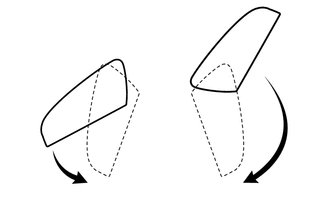
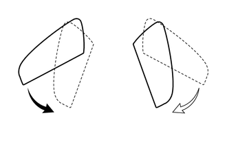
4. CHECK REVERSE SHIFT-LINKED OPERATION OF MIRRORS
(a) Turn the ignition switch ON.
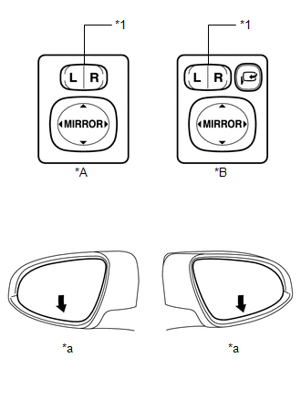
(b) Set the mirror select switch to L or R.
Text in Illustration|
*A |
w/o Retract Mirror |
|
*B |
w/ Retract Mirror |
|
*1 |
Mirror Select Switch |
|
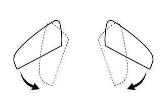
*a |
Downward |
(c) Check that the mirror surface turns downward when the shift lever is moved to R.
(d) Check that the mirror surface position returns to the original position when one of the following conditions is met:
- Shift lever is moved to any position other than R.
- Mirror select switch is in the neutral position (off).
- Ignition switch is turned off.
5. CHECK MEMORY CALL FUNCTION
(a) Memory call function check
(1) With a electrical key transmitter sub-assembly or door control transmitter assembly recognition code registered:
Perform a wireless door unlock operation and check that opening the driver side door causes the following:
- The buzzer sounds for 0.1 seconds.
- The front seat and outer mirror surface position automatically move to the stored positions.
HINT:
- The registered electrical key transmitter sub-assembly or door control transmitter assembly recognition code is recalled automatically.
- If the memory call function is not operated, the buzzer will not sound.
(b) With the ignition switch off and the driver door closed, press and hold the M1 or M2 switch while carrying the electrical key transmitter sub-assembly or door control transmitter assembly. The main body ECU (driver side junction block assembly) will enter electrical key transmitter sub-assembly or door control transmitter assembly recognition code registration mode to allow a key to be linked to mirror surface memory position.
HINT:
If the memory switch is released before entering registration mode, the memory switch will not enter registration mode.
(c) When the manual door lock switch is pressed, check that the buzzer of the position control ECU and switch assembly sounds once (0.5 seconds).
(d) With the ignition switch off and the driver side door closed, press and hold the SET switch while carrying the electrical key transmitter sub-assembly or door control transmitter assembly. The main body ECU (driver side junction block assembly) will enter electrical key transmitter sub-assembly or door control transmitter assembly recognition code deletion mode.
HINT:
If the memory switch is released before entering deletion mode, the memory switch will not enter deletion mode.
(e) When the manual door lock switch is pressed, check that the buzzer of the position control ECU and switch assembly sounds twice (0.1 seconds each time).
6. EMERGENCY STOP FUNCTION
(a) While a memory call function is operating, check that any one of the following actions will stop the memory call operation: 1) pressing the SET, M1or M2 switch, 2) moving the shift lever to R, 3) moving the mirror surface manually, or 4) moving the mirror surface to the uppermost, lowermost, leftmost or rightmost position.
 How To Proceed With Troubleshooting
CAUTION / NOTICE / HINT
HINT:
Use the following procedure to troubleshoot the power mirror control
system.
*: Use the Techstream.
PROCEDURE
1.
VEHICLE ...
 Problem Symptoms Table
PROBLEM SYMPTOMS TABLE
HINT:
Use the table below to help determine the cause of problem symptoms.
If multiple suspected areas are listed, the potential causes of the symptoms
are lis ...
Other materials about Toyota Venza:
SFR Solenoid Circuit (C0226/21,C0236/22,C0246/23,C0256/24,C1225/25-C1228/28)
DESCRIPTION
These solenoids turn on when signals are received from the skid control ECU and
they control the pressure acting on the wheel cylinders to control the braking force.
DTC Code
DTC Detection Condition
Trouble Area ...
Registered Device cannot be Deleted
PROCEDURE
1.
DELETE OPERATION
(a) Check if a registered portable player can be deleted normally.
OK:
Registered portable player can be deleted normally.
OK
END
NG
PROCEED TO ...
Initialization
INITIALIZATION
1. INITIALIZE SLIDING ROOF ECU (SLIDING ROOF DRIVE GEAR SUB-ASSEMBLY)
NOTICE:
When the sliding roof glass, sliding roof housing or sliding roof ECU
(sliding roof drive gear sub-assembly) is replaced or removed and installed,
t ...

0.1337