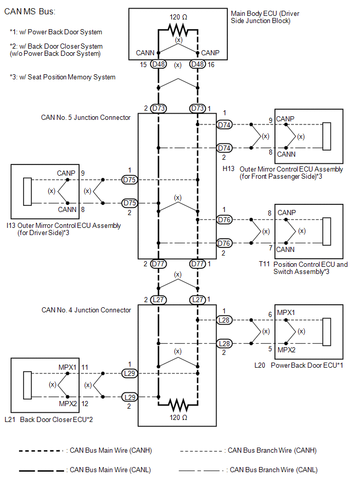
Toyota Venza: Lost Communication with Gateway Module (MS Bus) (U1002)
DESCRIPTION
- The main body ECU will store this DTC when no signals can be received from the ECUs that have been memorized as those that are connected to the CAN MS bus.
- When the main body ECU receives a response signal from the ECUs connected to the CAN MS bus, the main body ECU recognizes and memorizes that the ECU is connected to the CAN MS bus. Based on this memorized data, the main body ECU monitors for malfunctions in the ECUs connected to the CAN MS bus when communicating with those ECUs. If the main body ECU cannot receive response signals from the ECUs that have been memorized as those connected to the CAN MS bus, the main body ECU determines that a malfunction exists.
|
DTC No. |
DTC Detection Condition |
Trouble Area |
|---|---|---|
|
U1002 |
Main body ECU cannot receive signals from all ECUs that have been memorized as those connected to the CAN MS bus. |
|
- *1: w/ Power back door system
- *2: w/ Back door closer system (w/o power back door system)
WIRING DIAGRAM
CAUTION / NOTICE / HINT
NOTICE:
- Turn the ignition switch off before measuring the resistances between CAN bus main wires and between CAN bus branch wires.
- Turn the ignition switch off before inspecting CAN bus wires for a ground short.
- After the ignition switch is turned off, check that the key reminder warning system and light reminder warning system are not operating.
- Before measuring the resistance, leave the vehicle as is for at least 1 minute and do not operate the ignition switch, any other switches or the doors. If any doors need to be opened in order to check connectors, open the doors and leave them open.
HINT:
- Operating the ignition switch, any other switches or a door triggers related ECU and sensor communication on the CAN. This communication will cause the resistance value to change.
- Even after DTCs are cleared, if a DTC is stored again after driving the vehicle for a while, the malfunction may be occurring due to vibration of the vehicle. In such a case, wiggling the ECUs or wire harness while performing the inspection below may help determine the cause of the malfunction.
PROCEDURE
|
1. |
CHECK CAN MS BUS WIRE |
(a) Turn the ignition switch off.
|
(b) Measure the resistance according to the value(s) in the table below. Standard Resistance:
|
|
(c) Disconnect the cable from the negative (-) battery terminal.
(d) Measure the resistance according to the value(s) in the table below.
Standard Resistance:
|
Tester Connection |
Condition |
Specified Condition |
Result |
|---|---|---|---|
|
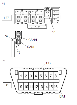
L27-1 (CANH) - D1-16 (BAT) |
Cable disconnected from negative (-) battery terminal |
6 kΩ or higher |
Below 6 kΩ: CANH +B short |
|
L27-2 (CANL) - D1-16 (BAT) |
Cable disconnected from negative (-) battery terminal |
6 kΩ or higher |
Below 6 kΩ: CANL +B short |
|
Result |
Proceed to |
|---|---|
|
OK |
A |
|
Open in CAN main bus line |
B |
|
C |
| A | .gif) |
REPLACE MAIN BODY ECU (DRIVER SIDE JUNCTION BLOCK) |
| C | |
GO TO STEP 6 |
|
.gif)
|
2. |
CHECK FOR OPEN IN CAN MS BUS MAIN WIRE (CAN NO. 4 J/C - CAN NO. 5 J/C) |
|
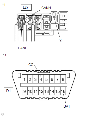
(a) Disconnect the CAN No. 4 junction connector (L27). Text in Illustration
|
|
(b) Measure the resistance according to the value(s) in the table below.
Standard Resistance:
|
Tester Connection |
Condition |
Specified Condition |
|---|---|---|
|
L27-1 (CANH) - L27-2 (CANL) |
Ignition switch off |
108 to 132 Ω |
| OK | |
REPLACE CAN NO. 4 J/C |
|
|
3. |
CHECK FOR OPEN IN CAN MS BUS MAIN WIRE (CAN NO. 5 J/C - CAN NO. 4 J/C) |
(a) Reconnect CAN No. 4 junction connector (L27).
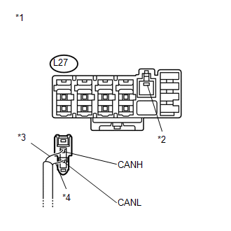
(b) Disconnect the CAN No. 5 junction connector (D77).
 Text in Illustration
|
*1 |
CAN No. 5 Junction Connector |
|
*2 |
Rear view of wire harness connector (to CAN No. 5 Junction Connector) |
|
*3 |
Red |
|
*4 |
White |
(c) Measure the resistance according to the value(s) in the table below.
Standard Resistance:
|
Tester Connection |
Condition |
Specified Condition |
|---|---|---|
|
D77-1 (CANH) - D77-2 (CANL) |
Ignition switch off |
108 to 132 Ω |
| NG | |
REPAIR OR REPLACE CAN MS BUS MAIN WIRE OR CONNECTOR (CAN NO. 5 J/C - CAN NO. 4 J/C) |
|
|
4. |
CHECK FOR OPEN IN CAN MS BUS MAIN WIRE (CAN NO. 5 J/C - MAIN BODY ECU) |
(a) Disconnect the CAN No. 5 junction connector (D73).
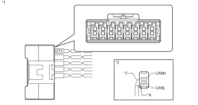 Text in Illustration
|
*1 |
CAN No. 5 Junction Connector |
|
*2 |
Rear view of wire harness connector (to CAN No. 5 Junction Connector) |
|
*3 |
Sky Blue |
|
*4 |
White |
(b) Measure the resistance according to the value(s) in the table below.
Standard Resistance:
|
Tester Connection |
Condition |
Specified Condition |
|---|---|---|
|
D73-1 (CANH) - D73-2 (CANL) |
Ignition switch off |
108 to 132 Ω |
| OK | |
REPLACE CAN NO. 5 J/C |
|
|
5. |
CHECK FOR OPEN IN CAN MS BUS MAIN WIRE (MAIN BODY ECU - CAN NO. 5 J/C) |
(a) Reconnect the No. 5 junction connector (D73).
|
(b) Disconnect the main body ECU connector (D48). Text in Illustration
|
|
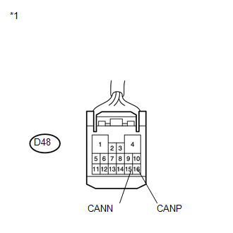
(c) Measure the resistance according to the value(s) in the table below.
Standard Resistance:
|
Tester Connection |
Condition |
Specified Condition |
|---|---|---|
|
D48-16 (CANP) - D48-15 (CANN) |
Ignition switch off |
108 to 132 Ω |
| OK | |
REPLACE MAIN BODY ECU (DRIVER SIDE JUNCTION BLOCK) |
| NG | |
REPAIR OR REPLACE CAN MS BUS MAIN WIRE OR CONNECTOR (MAIN BODY ECU - CAN NO. 5 J/C) |
|
6. |
CHECK FOR SHORT IN CAN BUS WIRE (CAN NO. 4 J/C) |
(a) Turn the ignition switch off.
|
(b) Disconnect the CAN No. 4 junction connector (L27). Text in Illustration
|
|
(c) Measure the resistance according to the value(s) in the table below.
Standard Resistance:
|
Tester Connection |
Condition |
Specified Condition |
Purpose |
|---|---|---|---|
|
L27-1 (CANH) - L27-2 (CANL) |
Ignition switch off |
108 to 132 Ω |
Inspection for open or short circuit between bus line |
|
L27-1 (CANH) - D1-4 (CG) |
Ignition switch off |
200 Ω or higher |
Inspection for CANH ground short |
|
L27-2 (CANL) - D1-4 (CG) |
Ignition switch off |
200 Ω or higher |
Inspection for CANL ground short |
|
L27-1 (CANH) - D1-16 (BAT) |
Cable disconnected from negative (-) battery terminal |
6 kΩ or higher |
Inspection for CANH +B short |
|
L27-2 (CANL) - D1-16 (BAT) |
Cable disconnected from negative (-) battery terminal |
6 kΩ or higher |
Inspection for CANL +B short |
HINT:
It is only necessary to perform the inspection in the above table for the result (open or short circuit) that was obtained in the Check CAN MS Bus Wire inspection.
Find the necessary inspection from the Purpose column that matches the result in the Result column from the Check CAN MS Bus Wire inspection.
|
Result |
Proceed to |
|---|---|
|
OK (w/ Power back door system) |
A |
|
OK (w/ Back door closer system) |
B |
|
NG |
C |
| B | |
GO TO STEP 9 |
| C | |
GO TO STEP 11 |
|
|
7. |
CHECK FOR SHORT IN CAN MS BUS WIRES (POWER BACK DOOR ECU - CAN NO. 4 J/C) |
(a) Reconnect the CAN No. 4 junction connector (L27).
|
(b) Disconnect the power back door ECU connector. Text in Illustration
|
|

(c) Measure the resistance according to the value(s) in the table below.
Standard Resistance:
|
Tester Connection |
Condition |
Specified Condition |
Purpose |
|---|---|---|---|
|
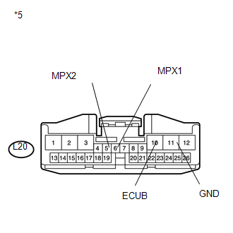
L20-6 (MPX1) - L20-5 (MPX2) |
Ignition switch off |
54 to 69 Ω |
Inspection for open or short circuit between bus lines |
|
L20-6 (MPX1) - L20-11 (GND) |
Ignition switch off |
200 Ω or higher |
Inspection for CANH ground short |
|
L20-5 (MPX2) - L20-11 (GND) |
Ignition switch off |
200 Ω or higher |
Inspection for CANL ground short |
|
L20-6 (MPX1) - L20-10 (ECUB) |
Cable disconnected from negative (-) battery terminal |
6 kΩ or higher |
Inspection for CANH +B short |
|
L20-5 (MPX2) - L20-10 (ECUB) |
Cable disconnected from negative (-) battery terminal |
6 kΩ or higher |
Inspection for CANL +B short |
HINT:
It is only necessary to perform the inspection in the above table for the result (open or short circuit) that was obtained in the Check CAN MS Bus Wire inspection.
Find the necessary inspection from the Purpose column that matches the result in the Result column from the Check CAN MS Bus Wire inspection.
| OK | |
REPLACE MULTIPLEX NETWORK DOOR ECU (POWER BACK DOOR ECU) |
|
|
8. |
CHECK CAN MS BUS BRANCH WIRE (POWER BACK DOOR ECU) |
|
(a) Disconnect the CAN No. 4 junction connector (L28). Text in Illustration
|
|
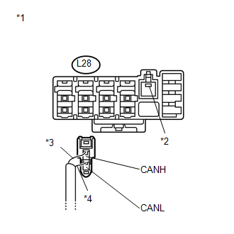
|
(b) Measure the resistance according to the value(s) in the table below. Standard Resistance:
|
|
|
*5 |
Front view of wire harness connector: (to Power Back Door ECU) |
HINT:
It is only necessary to perform the inspection in the above table for the result (open or short circuit) that was obtained in the Check CAN MS Bus Wire inspection.
Find the necessary inspection from the Purpose column that matches the result in the Result column from the Check CAN MS Bus Wire inspection.
| OK | |
REPLACE CAN NO. 4 J/C |
| NG | |
REPAIR OR REPLACE CAN MS BUS BRANCH WIRE OR CONNECTOR (POWER BACK DOOR ECU) |
|
9. |
CHECK FOR SHORT IN CAN MS BUS WIRES (BACK DOOR CLOSER ECU - CAN NO. 4 J/C) |
(a) Reconnect the CAN No. 4 junction connector (L27).
|
(b) Disconnect the back door closer ECU connector. Text in Illustration
|
|
.png)
(c) Measure the resistance according to the value(s) in the table below.
Standard Resistance:
|
Tester Connection |
Condition |
Specified Condition |
Purpose |
|---|---|---|---|
|
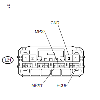
L21-11 (MPX1) - L21-12 (MPX2) |
Ignition switch off |
54 to 69 Ω |
Inspection for open or short circuit between bus lines |
|
L21-11 (MPX1) - L21-3 (GND) |
Ignition switch off |
200 Ω or higher |
Inspection for CANH ground short |
|
L21-12 (MPX2) - L21-3 (GND) |
Ignition switch off |
200 Ω or higher |
Inspection for CANL ground short |
|
L21-11 (MPX1) - L21-16 (ECUB) |
Cable disconnected from negative (-) battery terminal |
6 kΩ or higher |
Inspection for CANH +B short |
|
L21-12 (MPX2) - L21-16 (ECUB) |
Cable disconnected from negative (-) battery terminal |
6 kΩ or higher |
Inspection for CANL +B short |
HINT:
It is only necessary to perform the inspection in the above table for the result (open or short circuit) that was obtained in the Check CAN MS Bus Wire inspection.
Find the necessary inspection from the Purpose column that matches the result in the Result column from the Check CAN MS Bus Wire inspection.
| OK | |
REPLACE MULTIPLEX NETWORK DOOR ECU (BACK DOOR CLOSER ECU) |
|
|
10. |
CHECK CAN MS BUS BRANCH WIRE (BACK DOOR CLOSER ECU) |
|
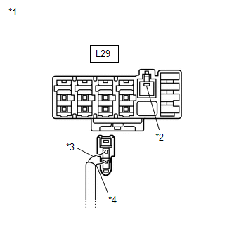
(a) Disconnect the CAN No. 4 junction connector (L29). Text in Illustration
|
|
|
(b) Measure the resistance according to the value(s) in the table below. Standard Resistance:
HINT: It is only necessary to perform the inspection in the above table for the result (open or short circuit) that was obtained in the Check CAN MS Bus Wire inspection. Find the necessary inspection from the Purpose column that matches the result in the Result column from the Check CAN MS Bus Wire inspection. |
|
| OK | |
REPLACE CAN NO. 4 J/C |
| NG | |
REPAIR OR REPLACE CAN MS BUS BRANCH WIRE OR CONNECTOR (BACK DOOR CLOSER ECU) |
|
11. |
CHECK FOR SHORT IN CAN MS BUS WIRES (CAN NO. 5 J/C - CAN NO. 4 J/C) |
(a) Reconnect the CAN No. 4 junction connector (L27).
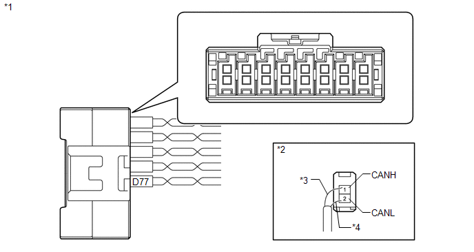
(b) Disconnect the CAN No. 5 junction connector (D77).
 Text in Illustration
|
*1 |
CAN No. 5 Junction Connector |
|
*2 |
Rear view of wire harness connector (to CAN No. 5 Junction Connector) |
|
*3 |
DLC3 |
|
*4 |
Red |
|
*5 |
White |
(c) Measure the resistance according to the value(s) in the table below.
Standard Resistance:
|
Tester Connection |
Condition |
Specified Condition |
Purpose |
|---|---|---|---|
|
D77-1 (CANH) - D77-2 (CANL) |
Ignition switch off |
108 to 132 Ω |
Inspection for open or short circuit between bus line |
|
D77-1 (CANH) - D1-4 (CG) |
Ignition switch off |
200 Ω or higher |
Inspection for CANH ground short |
|
D77-2 (CANL) - D1-4 (CG) |
Ignition switch off |
200 Ω or higher |
Inspection for CANL ground short |
|
D77-1 (CANH) - D1-16 (BAT) |
Cable disconnected from negative (-) battery terminal |
6 kΩ or higher |
Inspection for CANH +B short |
|
D77-2 (CANL) - D1-16 (BAT) |
Cable disconnected from negative (-) battery terminal |
6 kΩ or higher |
Inspection for CANL +B short |
HINT:
It is only necessary to perform the inspection in the above table for the result (open or short circuit) that was obtained in the Check CAN MS Bus Wire inspection.
Find the necessary inspection from the Purpose column that matches the result in the Result column from the Check CAN MS Bus Wire inspection.
| NG | |
REPAIR OR REPLACE CAN MS BUS MAIN WIRE OR CONNECTOR (CAN NO. 5 J/C - CAN NO. 4 J/C) |
|
|
12. |
CHECK FOR SHORT IN CAN MS BUS WIRES (CAN NO. 5 J/C - POSITION CONTROL ECU AND SWITCH ASSEMBLY) |
(a) Disconnect the CAN No. 5 junction connector (D76).
(b) Reconnect the CAN No. 5 junction connector (D77).
 Text in Illustration
|
*1 |
CAN No. 5 Junction Connector |
|
*2 |
Rear view of wire harness connector (to CAN No. 5 Junction Connector) |
|
*3 |
DLC3 |
|
*4 |
Green |
|
*5 |
Red |
(c) Measure the resistance according to the value(s) in the table below.
Standard Resistance:
|
Tester Connection |
Condition |
Specified Condition |
Purpose |
|---|---|---|---|
|
D76-1 (CANH) - D76-2 (CANL) |
Ignition switch off |
200 Ω or higher |
Inspection for open or short circuit between bus line |
|
D76-1 (CANH) - D1-4 (CG) |
Ignition switch off |
200 Ω or higher |
Inspection for CANH ground short |
|
D76-2 (CANL) - D1-4 (CG) |
Ignition switch off |
200 Ω or higher |
Inspection for CANL ground short |
|
D76-1 (CANH) - D1-16 (BAT) |
Cable disconnected from negative (-) battery terminal |
6 kΩ or higher |
Inspection for CANH +B short |
|
D76-2 (CANL) - D1-16 (BAT) |
Cable disconnected from negative (-) battery terminal |
6 kΩ or higher |
Inspection for CANL +B short |
HINT:
It is only necessary to perform the inspection in the above table for the result (open or short circuit) that was obtained in the Check CAN MS Bus Wire inspection.
Find the necessary inspection from the Purpose column that matches the result in the Result column from the Check CAN MS Bus Wire inspection.
| NG | |
GO TO STEP 16 |
|
|
13. |
CHECK FOR SHORT IN CAN MS BUS WIRES (CAN NO. 5 J/C - OUTER MIRROR CONTROL ECU ASSEMBLY (for Driver Side)) |
(a) Disconnect the CAN No. 5 junction connector (D75).
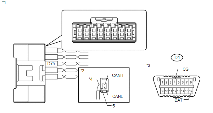 Text in Illustration
|
*1 |
CAN No. 5 Junction Connector |
|
*2 |
Rear view of wire harness connector (to CAN No. 5 Junction Connector) |
|
*3 |
DLC3 |
|
*4 |
Blue |
|
*5 |
White |
(b) Measure the resistance according to the value(s) in the table below.
Standard Resistance:
|
Tester Connection |
Condition |
Specified Condition |
Purpose |
|---|---|---|---|
|
D75-1 (CANH) - D75-2 (CANL) |
Ignition switch off |
200 Ω or higher |
Inspection for open or short circuit between bus line |
|
D75-1 (CANH) - D1-4 (CG) |
Ignition switch off |
200 Ω or higher |
Inspection for CANH ground short |
|
D75-2 (CANL) - D1-4 (CG) |
Ignition switch off |
200 Ω or higher |
Inspection for CANL ground short |
|
D75-1 (CANH) - D1-16 (BAT) |
Cable disconnected from negative (-) battery terminal |
6 kΩ or higher |
Inspection for CANH +B short |
|
D75-2 (CANL) - D1-16 (BAT) |
Cable disconnected from negative (-) battery terminal |
6 kΩ or higher |
Inspection for CANL +B short |
HINT:
It is only necessary to perform the inspection in the above table for the result (open or short circuit) that was obtained in the Check CAN MS Bus Wire inspection.
Find the necessary inspection from the Purpose column that matches the result in the Result column from the Check CAN MS Bus Wire inspection.
| NG | |
GO TO STEP 17 |
|
|
14. |
CHECK FOR SHORT IN CAN MS BUS WIRES (CAN NO. 5 J/C - OUTER MIRROR CONTROL ECU ASSEMBLY (for Front Passenger Side)) |
(a) Disconnect the CAN No. 5 junction connector (D74).
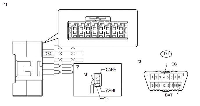 Text in Illustration
|
*1 |
CAN No. 5 Junction Connector |
|
*2 |
Rear view of wire harness connector (to CAN No. 5 Junction Connector) |
|
*3 |
DLC3 |
|
*4 |
Pink |
|
*5 |
White |
(b) Measure the resistance according to the value(s) in the table below.
Standard Resistance:
|
Tester Connection |
Condition |
Specified Condition |
Purpose |
|---|---|---|---|
|
D74-1 (CANH) - D74-2 (CANL) |
Ignition switch off |
200 Ω or higher |
Inspection for open or short circuit between bus line |
|
D74-1 (CANH) - D1-4 (CG) |
Ignition switch off |
200 Ω or higher |
Inspection for CANH ground short |
|
D74-2 (CANL) - D1-4 (CG) |
Ignition switch off |
200 Ω or higher |
Inspection for CANL ground short |
|
D74-1 (CANH) - D1-16 (BAT) |
Cable disconnected from negative (-) battery terminal |
6 kΩ or higher |
Inspection for CANH +B short |
|
D74-2 (CANL) - D1-16 (BAT) |
Cable disconnected from negative (-) battery terminal |
6 kΩ or higher |
Inspection for CANL +B short |
HINT:
It is only necessary to perform the inspection in the above table for the result (open or short circuit) that was obtained in the Check CAN MS Bus Wire inspection.
Find the necessary inspection from the Purpose column that matches the result in the Result column from the Check CAN MS Bus Wire inspection.
| NG | |
GO TO STEP 18 |
|
|
15. |
CHECK FOR SHORT IN CAN MS BUS WIRES (CAN NO. 5 J/C - MAIN BODY ECU) |
(a) Disconnect the CAN No. 5 junction connector (D73).
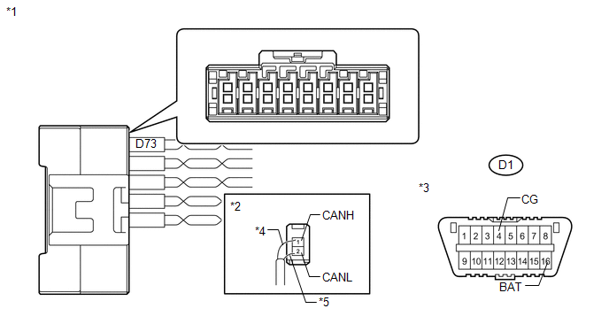 Text in Illustration
|
*1 |
CAN No. 5 Junction Connector |
|
*2 |
Rear view of wire harness connector (to CAN No. 5 Junction Connector) |
|
*3 |
DLC3 |
|
*4 |
Sky Blue |
|
*5 |
White |
(b) Measure the resistance according to the value(s) in the table below.
Standard Resistance:
|
Tester Connection |
Condition |
Specified Condition |
Purpose |
|---|---|---|---|
|
D73-1 (CANH) - D73-2 (CANL) |
Ignition switch off |
108 to 132 Ω |
Inspection for open or short circuit between bus line |
|
D73-1 (CANH) - D1-4 (CG) |
Ignition switch off |
200 Ω or higher |
Inspection for CANH ground short |
|
D73-2 (CANL) - D1-4 (CG) |
Ignition switch off |
200 Ω or higher |
Inspection for CANL ground short |
|
D73-1 (CANH) - D1-16 (BAT) |
Cable disconnected from negative (-) battery terminal |
6 kΩ or higher |
Inspection for CANH +B short |
|
D73-2 (CANL) - D1-16 (BAT) |
Cable disconnected from negative (-) battery terminal |
6 kΩ or higher |
Inspection for CANL +B short |
HINT:
It is only necessary to perform the inspection in the above table for the result (open or short circuit) that was obtained in the Check CAN MS Bus Wire inspection.
Find the necessary inspection from the Purpose column that matches the result in the Result column from the Check CAN MS Bus Wire inspection.
| OK | |
REPLACE CAN NO. 5 J/C |
| NG | |
GO TO STEP 19 |
|
16. |
CHECK FOR SHORT IN CAN MS BUS BRANCH WIRES (POSITION CONTROL ECU AND SWITCH ASSEMBLY) |
(a) Reconnect the CAN No. 5 junction connector (D76).
(b) Disconnect the position control ECU and switch assembly connectors (T10 and T11).
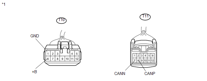 Text in Illustration
|
*1 |
Front view of wire harness connector (to Position Control ECU and Switch Assembly) |
(c) Measure the resistance according to the value(s) in the table below.
Standard Resistance:
|
Tester Connection |
Condition |
Specified Condition |
Purpose |
|---|---|---|---|
|
T11-8 (CANP) - T11-7 (CANN) |
Ignition switch off |
54 to 69 Ω |
Inspection for open or short circuit between bus line |
|
T11-8 (CANP) - T10-1 (GND) |
Ignition switch off |
200 Ω or higher |
Inspection for CANH ground short |
|
T11-7 (CANN) - T10-1 (GND) |
Ignition switch off |
200 Ω or higher |
Inspection for CANL ground short |
|
T11-8 (CANP) - T10-6 (+B) |
Cable disconnected from negative (-) battery terminal |
6 kΩ or higher |
Inspection for CANH +B short |
|
T11-7 (CANN) - T10-6 (+B) |
Cable disconnected from negative (-) battery terminal |
6 kΩ or higher |
Inspection for CANL +B short |
HINT:
It is only necessary to perform the inspection in the above table for the result (open or short circuit) that was obtained in the Check CAN MS Bus Wire inspection.
Find the necessary inspection from the Purpose column that matches the result in the Result column from the Check CAN MS Bus Wire inspection.
| OK | |
REPLACE POSITION CONTROL ECU AND SWITCH ASSEMBLY |
| NG | |
REPAIR OR REPLACE CAN MS BUS BRANCH WIRE OR CONNECTOR (POSITION CONTROL ECU AND SWITCH ASSEMBLY - CAN NO. 5 J/C) |
|
17. |
CHECK FOR SHORT IN CAN MS BUS BRANCH WIRES (OUTER MIRROR CONTROL ECU ASSEMBLY (for Driver Side)) |
(a) Reconnect the CAN No. 5 junction connector (D75).
|
(b) Disconnect the outer mirror control ECU assembly connector (I13). Text in Illustration
|
|
.png)
(c) Measure the resistance according to the value(s) in the table below.
Standard Resistance:
|
Tester Connection |
Condition |
Specified Condition |
Purpose |
|---|---|---|---|
|
I13-9 (CANP) - I13-8 (CANN) |
Ignition switch off |
54 to 69 Ω |
Inspection for open or short circuit between bus line |
|
I13-9 (CANP) - I13-7 (GND) |
Ignition switch off |
200 Ω or higher |
Inspection for CANH ground short |
|
I13-8 (CANN) - I13-7 (GND) |
Ignition switch off |
200 Ω or higher |
Inspection for CANL ground short |
|
I13-9 (CANP) - I13-6 (CPUB) |
Cable disconnected from negative (-) battery terminal |
6 kΩ or higher |
Inspection for CANH +B short |
|
I13-8 (CANN) - I13-6 (CPUB) |
Cable disconnected from negative (-) battery terminal |
6 kΩ or higher |
Inspection for CANL +B short |
HINT:
It is only necessary to perform the inspection in the above table for the result (open or short circuit) that was obtained in the Check CAN MS Bus Wire inspection.
Find the necessary inspection from the Purpose column that matches the result in the Result column from the Check CAN MS Bus Wire inspection.
| OK | |
REPLACE OUTER MIRROR CONTROL ECU ASSEMBLY (FOR DRIVER SIDE) |
| NG | |
REPAIR OR REPLACE CAN MS BUS BRANCH WIRE OR CONNECTOR (OUTER MIRROR CONTROL ECU ASSEMBLY (FOR DRIVER SIDE)) |
|
18. |
CHECK FOR SHORT IN CAN MS BUS BRANCH WIRES (OUTER MIRROR CONTROL ECU ASSEMBLY (for Front Passenger Side)) |
(a) Reconnect the CAN No. 5 junction connector (D74).
|
(b) Disconnect the outer mirror control ECU assembly connector (H13). Text in Illustration
|
|
.png)
(c) Measure the resistance according to the value(s) in the table below.
Standard Resistance:
|
Tester Connection |
Condition |
Specified Condition |
Purpose |
|---|---|---|---|
|
H13-9 (CANP) - H13-8 (CANN) |
Ignition switch off |
54 to 69 Ω |
Inspection for open or short circuit between bus line |
|
H13-9 (CANP) - H13-7 (GND) |
Ignition switch off |
200 Ω or higher |
Inspection for CANH ground short |
|
H13-8 (CANN) - H13-7 (GND) |
Ignition switch off |
200 Ω or higher |
Inspection for CANL ground short |
|
H13-9 (CANP) - H13-6 (CPUB) |
Cable disconnected from negative (-) battery terminal |
6 kΩ or higher |
Inspection for CANH +B short |
|
H13-8 (CANN) - H13-6 (CPUB) |
Cable disconnected from negative (-) battery terminal |
6 kΩ or higher |
Inspection for CANL +B short |
HINT:
It is only necessary to perform the inspection in the above table for the result (open or short circuit) that was obtained in the Check CAN MS Bus Wire inspection.
Find the necessary inspection from the Purpose column that matches the result in the Result column from the Check CAN MS Bus Wire inspection.
| OK | |
REPLACE OUTER MIRROR CONTROL ECU ASSEMBLY (FOR FRONT PASSENGER SIDE) |
| NG | |
REPAIR OR REPLACE CAN MS BUS BRANCH WIRE OR CONNECTOR (OUTER MIRROR CONTROL ECU ASSEMBLY (FOR FRONT PASSENGER SIDE) - CAN NO. 5 J/C) |
|
19. |
CHECK FOR SHORT IN CAN MS BUS WIRES (MAIN BODY ECU) |
(a) Reconnect the CAN No. 5 junction connector (D73).
(b) Disconnect the main body ECU connector (D48).
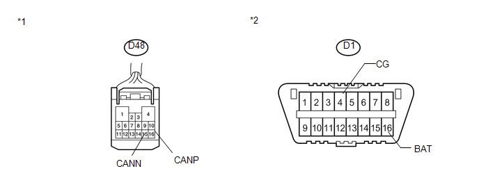 Text in Illustration
|
*1 |
Front view of wire harness connector (to Main Body ECU) |
|
*2 |
DLC3 |
(c) Measure the resistance according to the value(s) in the table below.
Standard Resistance:
|
Tester Connection |
Condition |
Specified Condition |
Purpose |
|---|---|---|---|
|
D48-16 (CANP) - D48-15 (CANN) |
Ignition switch off |
108 to 132 Ω |
Inspection for open or short circuit between bus line |
|
D48-16 (CANP) - D1-4 (CG) |
Ignition switch off |
200 Ω or higher |
Inspection for CANH ground short |
|
D48-15 (CANN) - D1-4 (CG) |
Ignition switch off |
200 Ω or higher |
Inspection for CANL ground short |
|
D48-16 (CANP) - D1-16 (BAT) |
Cable disconnected from negative (-) battery terminal |
6 kΩ or higher |
Inspection for CANH +B short |
|
D48-15 (CANN) - D1-16 (BAT) |
Cable disconnected from negative (-) battery terminal |
6 kΩ or higher |
Inspection for CANL +B short |
HINT:
It is only necessary to perform the inspection in the above table for the result (open or short circuit) that was obtained in the Check CAN MS Bus Wire inspection.
Find the necessary inspection from the Purpose column that matches the result in the Result column from the Check CAN MS Bus Wire inspection.
| OK | |
REPLACE MAIN BODY ECU (DRIVER SIDE JUNCTION BLOCK) |
| NG | |
REPAIR OR REPLACE CAN MS BUS MAIN WIRE OR CONNECTOR (MAIN BODY ECU - CAN NO. 5 J/C) |
 Lost Communication with Gateway Module (Power Management1) (U1002)
DESCRIPTION
The power management control ECU will store this DTC when no signals
can be received from the ECUs that have been memorized as those that are
connected to the CAN No. 2 bus ...
 Lost Communication with Gateway Module (Power Management2) (U1002)
DESCRIPTION
The power management control ECU will store this DTC when no signals
can be received from the ECUs that have been memorized as those that are
connected to the power managem ...
Other materials about Toyota Venza:
Engine
General Maintenance
GENERAL MAINTENANCE
CAUTION / NOTICE / HINT
HINT:
Perform these procedures after the engine has cooled down.
PROCEDURE
1. INSPECT DRIVE BELT
Engine Type
See Procedure
2GR-FE
See pag ...
Washer Nozzle(for Rear Side)
Components
COMPONENTS
ILLUSTRATION
On-vehicle Inspection
ON-VEHICLE INSPECTION
PROCEDURE
1. INSPECT REAR WASHER NOZZLE
(a) With the engine running, check where the washer fluid hits the windshield.
Standard Measurement
Area
...
Removal
REMOVAL
PROCEDURE
1. DISCONNECT CABLE FROM NEGATIVE BATTERY TERMINAL
CAUTION:
Wait at least 90 seconds after disconnecting the cable from the negative (-)
battery terminal to disable the SRS system.
NOTICE:
When disconnecting the cable, some systems ne ...

0.1129