Toyota Venza: Items to initialize
The following items must be initialized for normal system operation in cases such as after the battery is reconnected, or maintenance is performed on the vehicle.
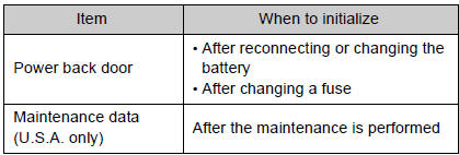
 Initialization
...
 For owners
Reporting safety defects for U.S. owners, and seat belt and SRS airbag instructions
for Canadian owners ...
Other materials about Toyota Venza:
Registration
REGISTRATION
CAUTION / NOTICE / HINT
NOTICE:
When the automatic transaxle is replaced, the transaxle compensation
code must be input into the TCM (proceed to Procedure 1). After the automatic
transaxle is reinstalled, the Quick Response (QR) ...
Speaker Circuit
DESCRIPTION
for 6 Speakers:
If there is a short in a speaker circuit, the navigation receiver assembly detects
it and stops output to the speakers.
Thus sound cannot be heard from the speakers even if there is no malfunction
in the navigation receiver a ...
Locking the driver’s doors from the outside without a key
Move the inside lock button to the
lock position.
Close the door.
►Vehicles with smart key system
The door cannot be locked if the “ENGINE START STOP” switch is in ACCESSORY or IGNITION
ON mode, or the electronic key is left inside the vehic ...

0.1546