Toyota Venza: Installation
INSTALLATION
PROCEDURE
1. INSTALL THERMOSTAT
(a) Install a new gasket to the thermostat.
|
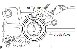
(b) Install the thermostat with the jiggle valve facing upward. HINT: The jiggle valve may be set to within 10° on either side of the prescribed position. |
|
2. INSTALL WATER INLET
|
(a) Install the water inlet with the 2 nuts. Torque: 10 N·m {102 kgf·cm, 7 ft·lbf} |
|
.png)
3. CONNECT NO. 2 RADIATOR HOSE
.gif)
4. INSTALL GENERATOR ASSEMBLY
5. INSTALL WIRE HARNESS CLAMP BRACKET
6. INSTALL V-RIBBED BELT
HINT:
See page
7. CONNECT CABLE TO NEGATIVE BATTERY TERMINAL
NOTICE:
When disconnecting the cable, some systems need to be initialized after the cable
is reconnected (See page ).
8. ADD ENGINE COOLANT
9. INSPECT FOR COOLANT LEAK
10. INSTALL COOL AIR INTAKE DUCT SEAL
11. INSTALL NO. 1 ENGINE UNDER COVER
12. INSTALL NO. 2 ENGINE UNDER COVER
13. INSTALL NO. 1 ENGINE COVER SUB-ASSEMBLY
 Inspection
INSPECTION
PROCEDURE
1. INSPECT THERMOSTAT
HINT:
The valve opening temperature is inscribed on the thermostat.
(a) Immerse the thermostat in water, and then gradually heat the water. ...
 Water Pump
...
Other materials about Toyota Venza:
Horn
Components
COMPONENTS
ILLUSTRATION
Inspection
INSPECTION
PROCEDURE
1. INSPECT LOW PITCHED HORN ASSEMBLY
(a) Apply battery voltage and check the operation of the low pitched
horn assembly according to the table below.
OK:
...
Problem Symptoms Table
PROBLEM SYMPTOMS TABLE
HINT:
Use the table below to help determine the cause of problem symptoms.
If multiple suspected areas are listed, the potential causes of the symptoms
are listed in order of probability in the "Suspected Area" ...
System Diagram
SYSTEM DIAGRAM
1. CAN AND DIRECT LINE SIGNALS
2. INPUT AND OUTPUT SIGNALS OF THE ACCESSORY METER ASSEMBLY
Warning light or indicator light
Communication Signal
Receiver
Communication Line
Sender
...

0.1816