Toyota Venza: Installation
INSTALLATION
PROCEDURE
1. INSTALL FRONT SEAT ASSEMBLY
(a) Place the front seat assembly in the cabin.
NOTICE:
Be careful not to damage the vehicle body.
(b) Connect each connector under the front seat assembly.
(c) Temporarily install the front seat assembly with the 4 bolts.
(d) Lift up the seat track adjusting handle and move the front seat assembly to the rearmost position.
|
(e) Tighten the 2 bolts on front side of the front seat assembly. Torque: 37 N·m {377 kgf·cm, 27 ft·lbf} HINT: Tighten the bolts in the order indicated in the illustration. |
|
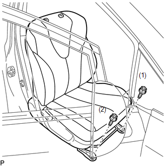
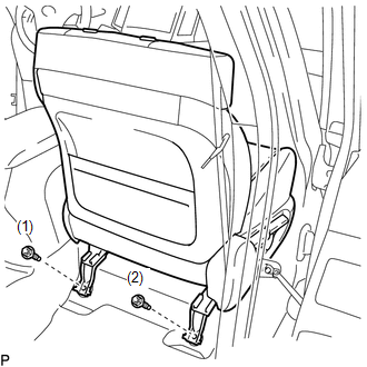
(f) Lift up the seat track adjusting handle and move the front seat assembly to the foremost position.
|
(g) Tighten the 2 bolts on rear side of the front seat assembly. Torque: 37 N·m {377 kgf·cm, 27 ft·lbf} HINT: Tighten the bolts in the order indicated in the illustration. |
|
2. INSPECT FRONT SEAT SLIDE ADJUSTER LOCK
(a) During sliding operation of the front seat assembly, check that the left and right seat adjusters move together smoothly and lock simultaneously.
If the seat adjusters do not lock simultaneously, loosen the bolts securing the front seat assembly to adjust the seat adjuster position.
3. INSTALL FRONT SEAT REAR INNER TRACK COVER
(a) Engage the 2 claws to install the front seat rear inner track cover.
4. INSTALL FRONT SEAT REAR OUTER TRACK COVER
(a) Engage the 2 claws to install the front seat rear outer track cover.
5. INSTALL FRONT SEAT HEADREST ASSEMBLY
6. CONNECT CABLE TO NEGATIVE BATTERY TERMINAL
NOTICE:
When disconnecting the cable, some systems need to be initialized after the cable
is reconnected (See page .gif) ).
).
7. INSPECT SRS WARNING LIGHT
(See page )
 Reassembly
REASSEMBLY
PROCEDURE
1. INSTALL FRONT SEAT WIRE
(a) Engage the 2 clamps to install the front seat wire.
(b) Connect the 4 connectors.
2. ...

Other materials about Toyota Venza:
Installation
INSTALLATION
PROCEDURE
1. INSTALL UNLOCK WARNING SWITCH
(a) Engage the 2 claws and install the unlock warning switch to the steering
column upper bracket.
(b) Extract the key.
(c) Co ...
Data List / Active Test
DATA LIST / ACTIVE TEST
1. DATA LIST
Using the Techstream to read the Data List allows the values or states of switches,
sensors, actuators and other items to be read without removing any parts. This non-intrusive
inspection can be very useful because in ...
Vehicle Speed Sensor "A" Intermittent / Erratic / High (P0503)
DESCRIPTION
If a malfunction (a rapid change in vehicle speed) in the vehicle speed signal
being output from the skid control ECU is detected while the cruise control is in
operation, the ECM determines that there is a momentary interruption or noise, and ...

0.1482