Toyota Venza: Inspection
INSPECTION
PROCEDURE
1. INSPECT FRONT POWER WINDOW REGULATOR MOTOR ASSEMBLY LH
|
(a) Apply positive (+) battery voltage to connector terminal 2 (B). NOTICE: Do not apply positive (+) battery voltage to any terminals other than terminal 2 (B) to avoid damaging the pulse sensor inside the motor. |
|
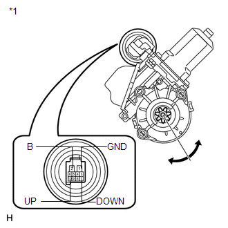
(b) Connect a ground lead to connector terminals 1 (GND) and 7 (DOWN) or 10 (UP).
(c) Check that the motor gear rotates smoothly as follows:
OK:
|
Measurement Condition |
Specified Condition |
|---|---|
|
Motor gear rotates clockwise (Up) |
|
Motor gear rotates counterclockwise (Down) |
|
*1 |
Component without harness connected (to Front Power Window Regulator Motor Assembly LH) |
- If the result is not as specified, replace the front power window regulator motor assembly LH.
CAUTION:
Reset the power window regulator motor (initialize the pulse sensor) after installing the power window regulator motor and regulator assembly onto the door.
2. INSPECT FRONT POWER WINDOW REGULATOR MOTOR ASSEMBLY RH
|
(a) Apply positive (+) battery voltage to connector terminal 2 (B). NOTICE: Do not apply positive (+) battery voltage to any terminals other than terminal 2 (B) to avoid damaging the pulse sensor inside the motor. |
|
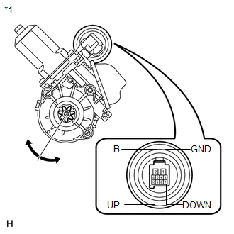
(b) Connect a ground lead to connector terminals 1 (GND) and 7 (DOWN) or 10 (UP).
(c) Check that the motor gear rotates smoothly as follows:
OK:
|
Measurement Condition |
Specified Condition |
|---|---|
|
Motor gear rotates counterclockwise (Up) |
|
Motor gear rotates clockwise (Down) |
|
*1 |
Component without harness connected (to Front Power Window Regulator Motor Assembly RH) |
- If the result is not as specified, replace the front power window regulator motor assembly RH.
CAUTION:
Reset the power window regulator motor (initialize the pulse sensor) after installing the power window regulator motor and regulator assembly onto the door.
 Removal
REMOVAL
CAUTION / NOTICE / HINT
HINT:
Use the same procedure for the RH side and LH side.
The procedure listed below is for the LH side.
PROCEDURE
1. DISCONNECT CABLE FROM NEGAT ...
 Installation
INSTALLATION
CAUTION / NOTICE / HINT
HINT:
Use the same procedure for the RH side and LH side.
The procedure listed below is for the LH side.
PROCEDURE
1. INSTALL FRONT POWER WI ...
Other materials about Toyota Venza:
Precaution
PRECAUTION
NOTICE:
When disconnecting the cable from the negative (-) battery terminal, initialize
the following systems after the cable is reconnected.
System Name
See Procedure
Power back door system
...
Check CAN Bus Line for Short to GND
DESCRIPTION
There may be a short circuit between the CAN bus main wire and GND when there
is no resistance between terminals 6 (CANH) and 4 (CG) or 14 (CANL) and 4 (CG) of
the DLC3.
Symptom
Trouble Area
No resistanc ...
If the engine will not start
If the engine still does not start after following the correct starting procedure
(, 175) or releasing the steering lock (, 176), confirm the following points.
- The engine will not start even if you are carrying the correct key.
One of the followi ...

0.1558