Toyota Venza: Fuel Sender Open Detected (B1500)
DESCRIPTION
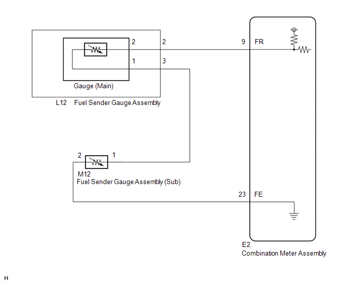
This DTC is output when the combination meter assembly detects a fuel sender gauge malfunction via the direct line.
|
DTC No. |
DTC Detection Condition |
Trouble Area |
|---|---|---|
|
B1500 |
When either of the following conditions is detected:
|
|
WIRING DIAGRAM
PROCEDURE
|
1. |
READ VALUE USING TECHSTREAM (FUEL INPUT) |
(a) Connect the Techstream to the DLC3.
(b) Turn the ignition switch to ON.
(c) Turn the Techstream on.
(d) Enter following menus: Body Electrical / Combination Meter / Data List.
(e) Check the values by referring to the table below.
Combination Meter|
Tester Display |
Measurement Item/Range |
Normal Condition |
Diagnostic Note |
|---|---|---|---|
|
Fuel Input |
Fuel input signal/Min.: 0, Max.: 127.5 |
The current fuel level displayed |
Unit: Liter |
|
Result |
Proceed to |
|---|---|
|
Fuel level data can be displayed on the Techstream and DTC B1500 is output. |
A |
|
Fuel level data cannot be displayed on the Techstream. |
B |
| A | .gif) |
REPLACE COMBINATION METER ASSEMBLY |
|
.gif)
|
2. |
INSPECT COMBINATION METER ASSEMBLY |
|
(a) Disconnect the E2 connector. |
|
(b) Measure the resistance according to the value(s) in the table below.
Standard Resistance:
|
Tester Connection |
Condition |
Specified Condition |
|---|---|---|
|
E2-9 (FR) - E2-23 (FE) |
Always |
6.5 to 187.2 Ω*1 |
|
E2-9 (FR) - E2-23 (FE) |
Always |
6.5 to 227.3 Ω*2 |
- *1: for Fuel Sender Gauge Assembly (Main)
- *2: for Fuel Sender Gauge Assembly (Sub)
|
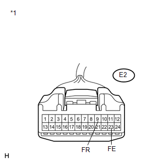
*1 |
Front view of wire harness connector (to Combination Meter Assembly) |
| OK | |
REPLACE COMBINATION METER ASSEMBLY |
|
|
3. |
CHECK HARNESS AND CONNECTOR (COMBINATION METER ASSEMBLY - FUEL SENDER GAUGE ASSEMBLY) |
(a) Disconnect the L12 connector.
(b) Measure the resistance according to the value(s) in the table below.
Standard Resistance:
|
Tester Connection |
Condition |
Specified Condition |
|---|---|---|
|
E2-9 (FR) - L12-2 |
Always |
Below 1 Ω |
|
E2-9 (FR) - Body ground |
Always |
10 kΩ or higher |
|
E2-23 (FE) - M12-2 |
Always |
Below 1 Ω |
|
E2-23 (FE) - Body ground |
Always |
10 kΩ or higher |
|
L12-3 - M12-1 |
Always |
Below 1 Ω |
|
M12-1 - Body ground |
Always |
10 kΩ or higher |
|
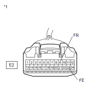
*1 |
Front view of wire harness connector (to Combination Meter Assembly) |
|
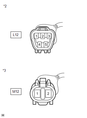
*2 |
Front view of wire harness connector (to Fuel Sender Gauge Assembly (Main)) |
|
*3 |
Front view of wire harness connector (to Fuel Sender Gauge Assembly (Sub)) |
| NG | |
REPAIR OR REPLACE HARNESS OR CONNECTOR |
|
|
4. |
INSPECT FUEL SENDER GAUGE ASSEMBLY |
(a) Remove the fuel sender gauge assembly (See page
.gif) (Main),
(Main),
(Sub)).
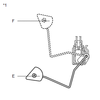
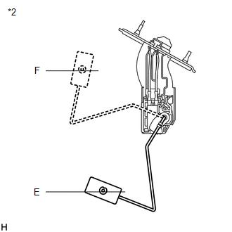
(b) Check that the float moves smoothly between E and F.
(c) Measure the resistance according to the value(s) in the table below.
Standard Resistance (Main):
|
Tester Connection |
Condition |
Specified Condition |
|---|---|---|
|
1 - 2 |
Float level is F (upper) |
6.5 to 8.5 Ω |
|
1 - 2 |
Float level is between F (upper) and E (lower) |
6.5 to 187.2 Ω (Gradually changes) |
|
1 - 2 |
Float level is E (lower) |
183.2 to 187.2 Ω |
Standard Resistance (Sub):
|
Tester Connection |
Condition |
Specified Condition |
|---|---|---|
|
1 - 2 |
Float level is F (upper) |
6.5 to 8.5 Ω |
|
1 - 2 |
Float level is between F (upper) and E (lower) |
6.5 to 227.3 Ω (Gradually changes) |
|
1 - 2 |
Float level is E (lower) |
222.3 to 227.3 Ω |
|
*1 |
Front view of wire harness connector (to Fuel Sender Gauge Assembly (Main)) |
|
*2 |
Front view of wire harness connector (to Fuel Sender Gauge Assembly (Sub)) |
|
Result |
Proceed to |
|---|---|
|
OK |
A |
|
NG (for 2GR-FE) |
B |
|
NG (for 1AR-FE) |
C |
| B | |
REPLACE FUEL SENDER GAUGE ASSEMBLY (for 2GR-FE) |
| C | |
REPLACE FUEL SENDER GAUGE ASSEMBLY (for 1AR-FE) |
|
|
5. |
CHECK FUEL SENDER GAUGE ASSEMBLY |
(a) Visually check for deformation on the fuel sender gauge assembly connector.
OK:
There is no deformation.
|
Result |
Proceed to |
|---|---|
|
OK |
A |
|
NG (for 2GR-FE) |
B |
|
NG (for 1AR-FE) |
C |
| A | |
REPLACE COMBINATION METER ASSEMBLY |
| B | |
REPLACE FUEL SENDER GAUGE ASSEMBLY (for 2GR-FE) |
| C | |
REPLACE FUEL SENDER GAUGE ASSEMBLY (for 1AR-FE) |
 On-vehicle Inspection
ON-VEHICLE INSPECTION
PROCEDURE
1. INSPECT SPEEDOMETER
(a) Check the operation.
(1) Using a speedometer tester (calibrated chassis dynamometer), check the speedometer
indication according to the ...
 Lost Communication with ECM / PCM "A" (U0100,U0129)
DESCRIPTION
The combination meter assembly communicates with the ECM via the CAN communication
system (CAN No. 1 Bus).
DTC No.
DTC Detection Condition
Trouble Area ...
Other materials about Toyota Venza:
Precaution
PRECAUTION
1. PRECAUTION FOR DISCONNECTING CABLE FROM NEGATIVE BATTERY TERMINAL
NOTICE:
After the ignition switch is turned off, the navigation receiver assembly
records various types of memory and settings. As a result, after turning
the ig ...
Operation Check
OPERATION CHECK
1. CHECK WINDOW LOCK SWITCH
HINT:
Before performing the window lock switch operation check, make sure that the
window lock switch is off (the switch is not pushed in).
(a) Check that the front passenger and rear windows cannot be operat ...
Installation
INSTALLATION
PROCEDURE
1. INSTALL STUD BOLT (for LH Side)
(a) Using SST and a socket wrench (21 mm), install the stud bolt.
Text in Illustration
*1
Socket Wrench
*2
...

0.175