Toyota Venza: Front Stabilizer Bar(for 2gr-fe 2wd)
Components
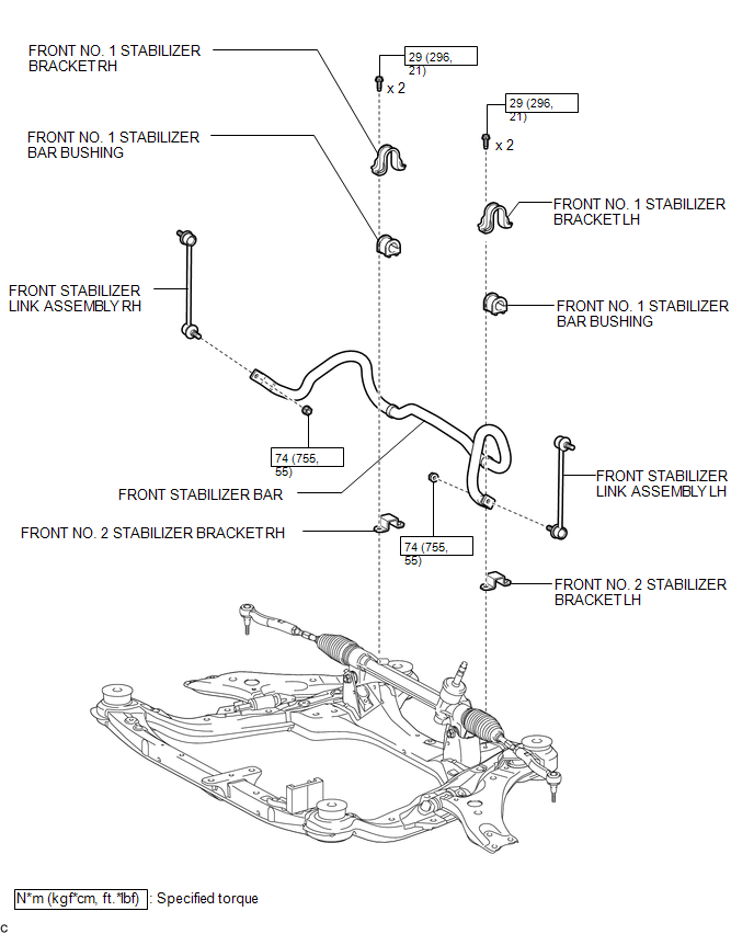
COMPONENTS
ILLUSTRATION
Removal
REMOVAL
PROCEDURE
1. REMOVE FRONT FRAME ASSEMBLY (When Using the Engine Support Bridge)
(See page .gif) )
)
2. REMOVE ENGINE ASSEMBLY WITH TRANSAXLE (When Not Using the Engine Support Bridge)
(See page )
3. SEPARATE FRONT STABILIZER LINK ASSEMBLY LH
|
(a) Remove the nut and separate the front stabilizer link assembly LH. HINT: If the ball joint turns together with the nut, use a hexagon wrench (6 mm) to hold the stud bolt. |
|
.png)
4. SEPARATE FRONT STABILIZER LINK ASSEMBLY RH
HINT:
Perform the same procedure as for the LH side.
5. REMOVE FRONT NO. 1 STABILIZER BRACKET LH
|
(a) Remove the 2 bolts and front No. 1 stabilizer bracket LH from the front frame assembly. |
|
.png)
6. REMOVE FRONT NO. 1 STABILIZER BRACKET RH
HINT:
Perform the same procedure as for the LH side.
7. REMOVE FRONT STABILIZER BAR
(a) Remove the front stabilizer bar from the front frame assembly.
8. REMOVE FRONT NO. 2 STABILIZER BRACKET LH
|
(a) Remove the front No. 2 stabilizer bracket LH from the front No. 1 stabilizer bar bushing. |
|
.png)
9. REMOVE FRONT NO. 2 STABILIZER BRACKET RH
HINT:
Perform the same procedure as for the LH side.
10. REMOVE FRONT NO. 1 STABILIZER BAR BUSHING
(a) Remove the 2 front No. 1 stabilizer bar bushings from the front stabilizer bar.
Inspection
INSPECTION
PROCEDURE
1. INSPECT FRONT STABILIZER LINK ASSEMBLY
|
(a) Inspect the turning torque of the ball joint. (1) Secure the front stabilizer link assembly in a vise using aluminum plates. (2) Install the nut to the front stabilizer link assembly stud. (3) Using a torque wrench, turn the nut continuously at a rate of 3 to 5 seconds per turn and take the torque reading on the 5th turn. Turning torque: 0.05 to 1.96 N*m (0.5 to 20 kgf*cm, 0.4 to 17 in.*lbf) If the turning torque is not within the specified range, replace the front stabilizer link assembly with a new one. |
|
.png)
(b) Inspect the dust cover.
(1) Check that the dust cover is not cracked and that there is no grease on it.
Installation
INSTALLATION
PROCEDURE
1. INSTALL FRONT NO. 1 STABILIZER BAR BUSHING
|
(a) Install the 2 front No. 1 stabilizer bar bushings to the front stabilizer bar as shown in the illustration. Text in Illustration
NOTICE: When installing the front No. 1 stabilizer bar bushings, make sure that the cutout faces the rear of the vehicle. |
|
.png)
2. INSTALL FRONT NO. 2 STABILIZER BRACKET LH
|
(a) Install the front No. 2 stabilizer bracket LH to the front No. 1 stabilizer bar bushing. |
|
.png)
3. INSTALL FRONT NO. 2 STABILIZER BRACKET RH
HINT:
Perform the same procedure as for the LH side.
4. INSTALL FRONT STABILIZER BAR
(a) Install the front stabilizer bar to the front frame assembly.
5. INSTALL FRONT NO. 1 STABILIZER BRACKET LH
|
(a) Install the front No. 1 stabilizer bracket LH to the front frame assembly with the 2 bolts. Torque: 29 N·m {296 kgf·cm, 21 ft·lbf} |
|
.png)
6. INSTALL FRONT NO. 1 STABILIZER BRACKET RH
HINT:
Perform the same procedure as for the LH side.
7. INSTALL FRONT STABILIZER LINK ASSEMBLY LH
|
(a) Install the front stabilizer link assembly LH with the nut. Torque: 74 N·m {755 kgf·cm, 55 ft·lbf} HINT: If the ball joint turns together with the nut, use a hexagon wrench (6 mm) to hold the stud bolt. |
|
.png)
8. INSTALL FRONT STABILIZER LINK ASSEMBLY RH
HINT:
Perform the same procedure as for the LH side.
9. INSTALL FRONT FRAME ASSEMBLY (When Using the Engine Support Bridge)
(See page .gif) )
)
10. INSTALL ENGINE ASSEMBLY WITH TRANSAXLE (When Not Using the Engine Support Bridge)
(See page )
 Front Stabilizer Bar(for 1ar-fe 2wd)
Components
COMPONENTS
ILLUSTRATION
Inspection
INSPECTION
PROCEDURE
1. INSPECT FRONT STABILIZER LINK ASSEMBLY
(a) Inspect the turning torque of the ball joint.
(1) Secure the ...

Other materials about Toyota Venza:
Unlock Warning Switch Circuit
DESCRIPTION
The key unlock warning switch assembly turns on when the ignition key is inserted
into the ignition key cylinder and turns off when the ignition key is removed.
The main body ECU (driver side junction block assembly) operates the key confinemen ...
Inspection
INSPECTION
PROCEDURE
1. INSPECT SHIFT LOCK CONTROL UNIT ASSEMBLY (w/o Smart Key System)
(a) Measure the voltage according to the value(s) in the table below.
Text in Illustration
*1
Component with harness c ...
Short in Front Pretensioner Squib RH Circuit (B1900/73-B1903/73)
DESCRIPTION
The front pretensioner squib RH circuit consists of the center airbag sensor
assembly and front seat outer belt assembly RH.
The center airbag sensor assembly uses this circuit to deploy the seat belt pretensioner
when deployment conditions a ...

0.176