Toyota Venza: Exterior
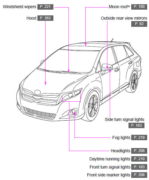
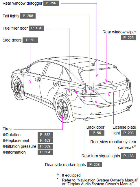
 Pictorial index
...
 Interior
...
Other materials about Toyota Venza:
Short in Front Passenger Side Squib 2nd Step Circuit (B1815/54-B1818/54)
DESCRIPTION
The front passenger side squib 2nd step circuit consists of the center airbag
sensor assembly and front passenger airbag assembly.
The center airbag sensor assembly uses this circuit to deploy the airbag when
deployment conditions are met.
T ...
Problem Symptoms Table
PROBLEM SYMPTOMS TABLE
NOTICE:
After replacing the stereo component tuner assembly of vehicles subscribed to
pay-type satellite radio broadcasts, XM radio ID registration is necessary (w/ SDARS
System).
HINT:
Use the table below to help determi ...
Reassembly
REASSEMBLY
PROCEDURE
1. INSTALL MULTIPLEX NETWORK DOOR ECU
(a) Connect the connector and install the multiplex network door ECU.
(b) Install the flat cable connector as shown in the illus ...

0.1637