Toyota Venza: Disassembly
DISASSEMBLY
PROCEDURE
1. DISCONNECT CABLE FROM NEGATIVE BATTERY TERMINAL
NOTICE:
When disconnecting the cable, some systems need to be initialized after the cable
is reconnected (See page .gif) ).
).
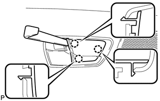
2. REMOVE REAR DOOR INSIDE HANDLE BEZEL PLUG
|
(a) Using a moulding remover, disengage the 3 claws and remove the rear door inside handle bezel plug. |
|
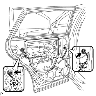
3. REMOVE REAR POWER WINDOW REGULATOR SWITCH ASSEMBLY WITH REAR DOOR ARMREST BASE PANEL
|
(a) Using a moulding remover, disengage the 2 clips and 5 claws. |
|
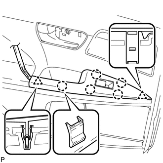
(b) Disconnect the connector and remove the rear power window regulator switch assembly with rear door armrest base panel.
4. REMOVE REAR DOOR TRIM BOARD SUB-ASSEMBLY
|
(a) Remove the 2 screws. |
|
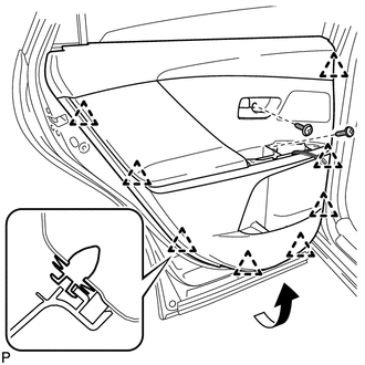
(b) Using a clip remover, disengage the 8 clips.
(c) Pull out the rear door trim board sub-assembly in the direction indicated by the arrow as shown in the illustration.
(d) Raise the rear door trim board sub-assembly and remove the rear door trim board sub-assembly together with the rear door inner glass weatherstrip.
|
(e) Disengage the 2 claws and disconnect the rear door inside handle sub-assembly. |
|
.png)
(f) for 13 Speakers:
(1) Disconnect the connector.
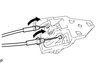
5. REMOVE REAR DOOR INSIDE HANDLE SUB-ASSEMBLY
|
(a) Disconnect the rear door lock remote control cable assembly and rear door inside locking cable assembly, and remove the rear door inside handle sub-assembly. |
|
6. REMOVE REAR DOOR INNER GLASS WEATHERSTRIP
|
(a) Disengage the 7 claws and remove the rear door inner glass weatherstrip from the rear door trim board sub-assembly as shown in the illustration. |
|
7. REMOVE REAR SPEAKER BRACKET (for 13 Speakers)
8. REMOVE REAR NO. 2 SPEAKER ASSEMBLY (for 13 Speakers)
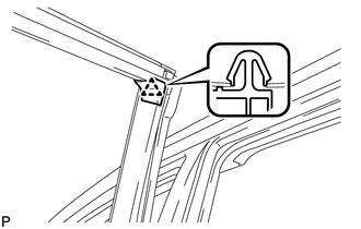
9. REMOVE REAR DOOR FRAME GARNISH
|
(a) Disengage the clip and remove the rear door frame garnish. HINT: This garnish needs to be replaced with a new one because the clip will break when removing the rear door frame garnish. |
|
10. REMOVE REAR SPEAKER ASSEMBLY
11. REMOVE REAR DOOR INSIDE PANEL REINFORCE SUB-ASSEMBLY
|
(a) Remove the 4 screws and rear door inside panel reinforce sub-assembly. |
|
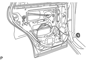
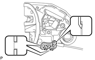
12. REMOVE REAR DOOR SERVICE HOLE COVER
|
(a) Disconnect the 2 connectors. |
|
(b) disengage the 2 clamps and remove the rear door service hole cover.
HINT:
Remove any remaining butyl tape from the door.
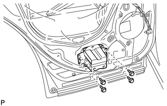
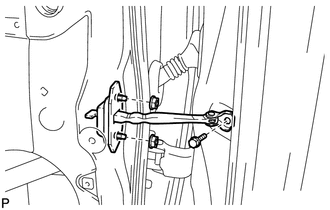
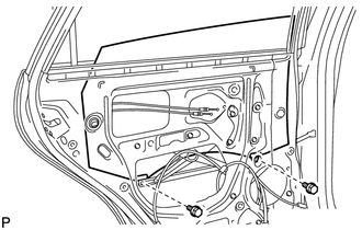
13. REMOVE REAR DOOR CHECK ASSEMBLY
|
(a) Remove the bolt, 2 nuts and rear door check assembly. |
|
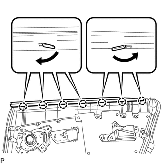
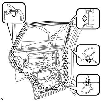
14. REMOVE REAR DOOR WEATHERSTRIP
|
(a) Using a clip remover, disengage the 21 clips and remove the front door weatherstrip. |
|
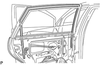
15. REMOVE REAR DOOR GLASS RUN
|
(a) Remove the rear door glass run. |
|
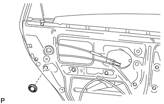
16. REMOVE REAR DOOR WINDOW DIVISION BAR SUB-ASSEMBLY
|
(a) Remove the hole plug. |
|
|
(b) Remove the 2 screws. |
|
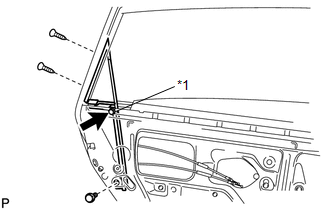
(c) Loosen the temporary bolt.
Text in Illustration|
*1 |
Temporary Bolt |
(d) Remove the bolt and rear door window division bar sub-assembly.
(e) Remove the temporary bolt from the rear door window division bar sub-assembly.
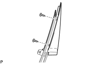
17. REMOVE REAR DOOR REAR GUIDE SEAL
|
(a) Remove the 2 screws and rear door rear guide seal. |
|
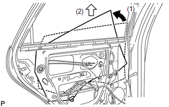
18. REMOVE REAR DOOR GLASS SUB-ASSEMBLY
|
(a) Remove the hole plug. |
|
(b) Connect the cable to the negative (-) battery terminal and the rear power window regulator motor connector.
(c) Connect the power window regulator switch assembly and move the rear door glass sub-assembly so that the door glass bolts can be seen.
(d) Disconnect the power window regulator switch assembly and the rear power window regulator motor connector.
(e) Disconnect the cable from the negative (-) battery terminal.
|
(f) Remove the 2 bolts. NOTICE: After the bolts are removed, do not allow the door glass to fall. |
|
|
(g) Remove the rear door glass sub-assembly as indicated by the arrows, in the order shown in the illustration. NOTICE: Do not damage the door glass. |
|
19. REMOVE REAR DOOR WINDOW REGULATOR ASSEMBLY
|
(a) Loosen the temporary bolt. Text in Illustration
NOTICE: Do not remove the temporary bolt. If the temporary bolt is removed, the rear door window regulator may fall and cause damage. |
|
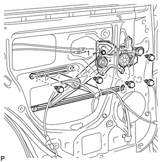
(b) Remove the 5 bolts.
(c) Remove the rear door window regulator assembly.
(d) Remove the temporary bolt from the rear door window regulator assembly.
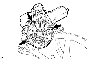
20. REMOVE REAR POWER WINDOW REGULATOR MOTOR ASSEMBLY
|
(a) Using a T25 "TORX" socket wrench, remove the 3 screws and the rear power window regulator motor assembly. |
|
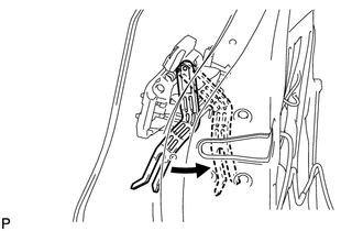
21. REMOVE REAR DOOR LOCK ASSEMBLY
|
(a) Using a T30 "TORX" socket wrench, remove the 3 screws. |
|
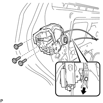
(b) Move the rear door lock assembly downward and pull the release plate out of the rear door outside handle frame.
|
(c) Remove the door lock wiring harness seal from the rear door lock assembly. |
|
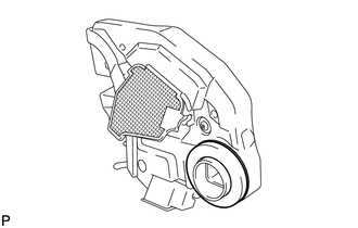
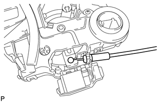
22. REMOVE REAR DOOR LOCK REMOTE CONTROL CABLE ASSEMBLY
|
(a) Using a screwdriver, disengage the claw. HINT: Tape the screwdriver tip before use. |
|
|
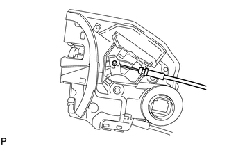
(b) Remove the rear door lock remote control cable assembly. |
|
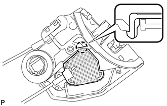
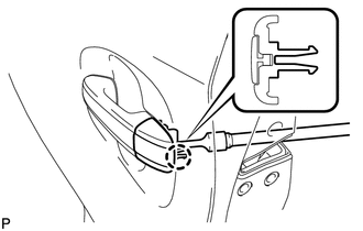
23. REMOVE REAR DOOR INSIDE LOCKING CABLE ASSEMBLY
|
(a) Using a screwdriver, disengage the 3 claws. HINT: Tape the screwdriver tip before use. |
|
|
(b) Remove the rear door inside locking cable assembly. |
|
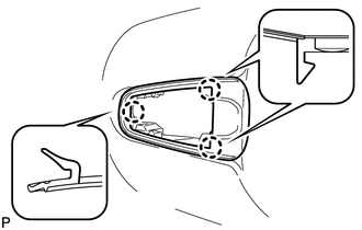
24. REMOVE REAR DOOR OUTSIDE HANDLE COVER
|
(a) Using a T30 "TORX" socket wrench, loosen the screw. HINT: The screw cannot be removed because it is integrated into the rear door outside handle frame sub-assembly. |
|
(b) Disengage the claw and remove the rear door outside handle cover.
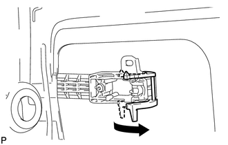
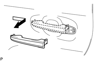
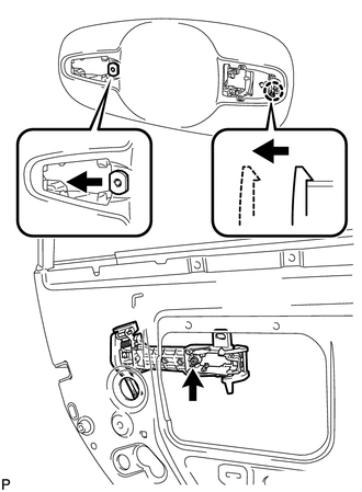
25. REMOVE REAR DOOR OUTSIDE HANDLE ASSEMBLY
|
(a) Pull and hold the release plate of the rear door outside handle frame sub-assembly as shown in the illustration. NOTICE: The release plate may interfere with the rear door outside handle assembly and may be damaged when removing the rear door outside handle assembly, unless the release plate of the rear door outside handle frame sub-assembly is pulled and held. |
|
|
(b) Move the lever in the direction indicated by the arrow in the illustration. |
|
|
(c) Remove the rear door outside handle assembly as shown in the illustration. |
|
26. REMOVE REAR DOOR FRONT OUTSIDE HANDLE PAD
|
(a) Disengage the 3 claws and remove the rear door front outside handle pad. |
|
27. REMOVE REAR DOOR REAR OUTSIDE HANDLE PAD
|
(a) Disengage the 2 claws and remove the rear door rear outside handle pad. |
|

28. REMOVE REAR DOOR OUTSIDE HANDLE FRAME SUB-ASSEMBLY
|
(a) Using a T30 "TORX" socket wrench, loosen the screw. |
|
(b) Slide the rear door outside handle frame sub-assembly to disengage the door handle nut and claw of the rear door outside handle frame sub-assembly, and then remove it.
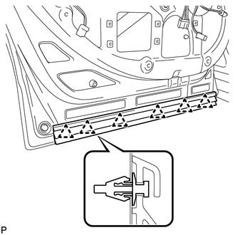
29. REMOVE REAR DOOR PANEL PROTECTOR
|
(a) Disengage the 6 clips and remove the rear door panel protector. |
|
30. REMOVE REAR DOOR BELT MOULDING
31. REMOVE REAR DOOR FRONT WINDOW FRAME MOULDING
32. REMOVE REAR DOOR REAR WINDOW FRAME MOULDING
33. REMOVE REAR DOOR UPPER WINDOW FRAME MOULDING
34. REMOVE REAR DOOR OUTSIDE STRIPE
35. REMOVE REAR DOOR LOWER OUTSIDE STRIPE
36. REMOVE NO. 2 BLACK OUT TAPE
37. REMOVE REAR DOOR OUTSIDE MOULDING
 Components
COMPONENTS
ILLUSTRATION
ILLUSTRATION
ILLUSTRATION
ILLUSTRATION
ILLUSTRATION
ILLUSTRATION
...
 Adjustment
ADJUSTMENT
CAUTION / NOTICE / HINT
CAUTION:
Before adjusting the door positions of vehicles equipped with side and curtain
shield airbags, be sure to disconnect the battery. After adjustment, c ...
Other materials about Toyota Venza:
Front Airbag Sensor RH Malfunction (B1610/13)
DESCRIPTION
The front airbag sensor RH circuit consists of the center airbag sensor assembly
and front airbag sensor RH.
The front airbag sensor RH detects impacts to the vehicle and sends signals to
the center airbag sensor assembly to determine if the ...
Installation
INSTALLATION
PROCEDURE
1. INSTALL REAR DOOR BELT MOULDING
(a) Engage the 5 claws to install the rear door belt moulding.
2. INSTALL REAR DOOR GLASS SUB-ASSEMBLY
3. INSTALL REAR DOOR WINDOW DIVIS ...
P/W Master Switch Communication Stop (B1206)
DESCRIPTION
This DTC is stored when LIN communication between the multiplex network master
switch assembly and main body ECU (driver side junction block assembly) stops for
more than 10 seconds.
DTC No.
DTC Detection Condition
...

0.1731