Toyota Venza: Disassembly
DISASSEMBLY
PROCEDURE
1. REMOVE TRANSPONDER KEY ECU ASSEMBLY (w/ Engine Immobiliser System)
.gif)
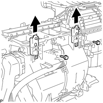
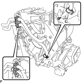
2. REMOVE NO. 1 FINISH PANEL MOUNTING BRACKET
|
(a) Remove the 2 bolts and 2 No. 1 finish panel mounting brackets as shown in the illustration. |
|
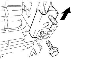
3. REMOVE NO. 2 FINISH PANEL MOUNTING BRACKET
|
(a) Remove the bolt and No. 2 finish panel mounting bracket as shown in the illustration. |
|
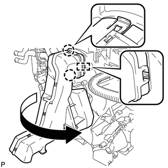
4. REMOVE NO. 3 AIR DUCT SUB-ASSEMBLY
|
(a) Disengage the 2 claws and guide, and remove the No. 3 air duct sub-assembly as shown in the illustration. |
|
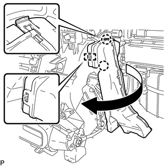
5. REMOVE NO. 2 AIR DUCT SUB-ASSEMBLY
|
(a) Disengage the 2 claws and guide, and remove the No. 2 air duct sub-assembly as shown in the illustration. |
|
6. REMOVE AIR CONDITIONING HARNESS ASSEMBLY
(a) Disconnect each connector.
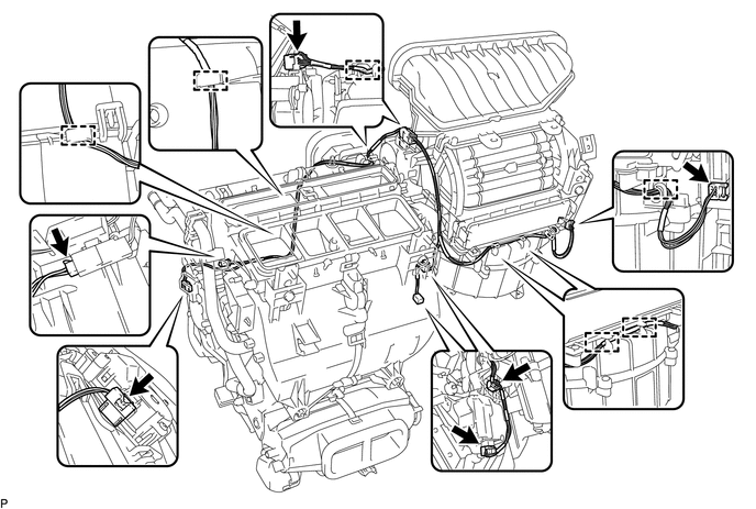
(b) Disengage each clamp and remove the air conditioning harness assembly.
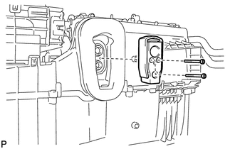
7. REMOVE COOLER EXPANSION VALVE
|
(a) Using a 4 mm hexagon wrench, remove the 2 hexagon bolts and cooler expansion valve. |
|
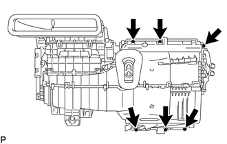
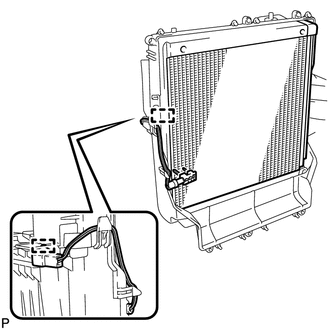
8. REMOVE AIR CONDITIONING RADIATOR ASSEMBLY
|
(a) Remove the 6 screws. |
|
|
(b) Disengage the guide and disconnect the wire harness. |
|
(c) Disengage the 5 claws and remove the air conditioning radiator assembly from the blower assembly with cooler evaporator sub-assembly.
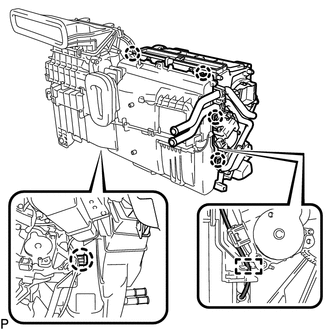
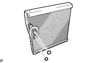
9. REMOVE COOLER EVAPORATOR SUB-ASSEMBLY
|
(a) Disengage the clamp and remove the cooler evaporator sub-assembly with the No. 1 cooler thermistor. |
|
|
(b) Remove the 2 O-rings from the cooler evaporator sub-assembly. |
|
10. REMOVE NO. 1 COOLER THERMISTOR
11. REMOVE ASPIRATOR PIPE
|
(a) Disengage the clamp. |
|
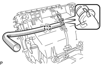
(b) Disengage the 2 claws and remove the aspirator pipe.
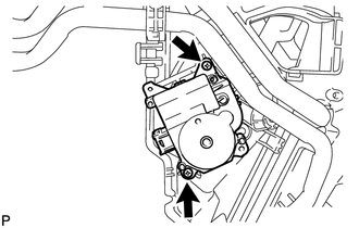
12. REMOVE AIR MIX CONTROL SERVO MOTOR SUB-ASSEMBLY
|
(a) Remove the 2 screws and air mix control servo motor sub-assembly. |
|
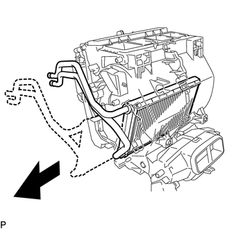
13. REMOVE HEATER RADIATOR UNIT SUB-ASSEMBLY
|
(a) Disengage the 3 claws and remove the heater clamp. Text in Illustration
|
|
(b) Remove the screw and clamp.
|
(c) Remove the heater radiator unit sub-assembly as shown in the illustration. NOTICE: Prepare a drain pan or cloth in case the cooling water leaks. |
|
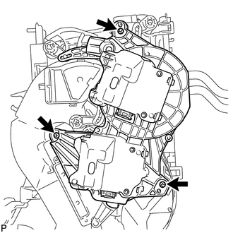
14. REMOVE AIR OUTLET CONTROL SERVO MOTOR SUB-ASSEMBLY
|
(a) Remove the 3 screws and air outlet control servo motor sub-assembly. |
|
 Removal
REMOVAL
CAUTION / NOTICE / HINT
NOTICE:
Make sure to select FACE mode before disconnecting the cable from the negative
(-) battery terminal.
PROCEDURE
1. RECOVER REFRIGERANT FROM REFRIGERATION ...
 Reassembly
REASSEMBLY
PROCEDURE
1. INSTALL AIR OUTLET CONTROL SERVO MOTOR SUB-ASSEMBLY
(a) Check that the slots, links and gears of the air outlet control servo
motor sub-assembly are positione ...
Other materials about Toyota Venza:
Back Door cannot be Opened
DESCRIPTION
When the back door cannot be opened, one of the following may be malfunctioning:
1) power back door ECU (power back door motor unit)*1 or back door closer ECU (multiplex
network door ECU)*2, 2) back door lock assembly, 3) back door opener swit ...
Components
COMPONENTS
ILLUSTRATION
ILLUSTRATION
ILLUSTRATION
ILLUSTRATION
ILLUSTRATION
ILLUSTRATION
...
Installation
INSTALLATION
PROCEDURE
1. INSTALL POWER DISTRIBUTION
(a) Connect the 3 connectors.
(b) Engage the 2 claws to temporarily install the power distribution
as shown in the illustration.
...

0.1877