Toyota Venza: Coolant Thermostat (Coolant Temperature Below Thermostat Regulating Temperature) (P0128)
DESCRIPTION
HINT:
This DTC relates to the thermostat.
This DTC is stored when the engine coolant temperature does not reach 75°C (167°F) despite sufficient engine warm-up time having elapsed.
|
DTC No. |
DTC Detection Condition |
Trouble Area |
|---|---|---|
|
P0128 |
|
|
MONITOR DESCRIPTION
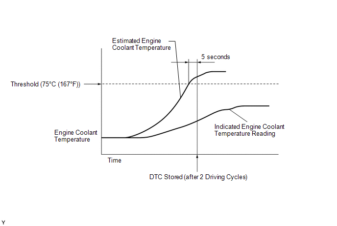
The ECM estimates the engine coolant temperature based on the starting temperature, engine loads, and engine speeds. The ECM then compares the estimated temperature with the actual engine coolant temperature. When the estimated engine coolant temperature reaches 75°C (167°F), the ECM checks the actual engine coolant temperature. If the actual engine coolant temperature is less than 75°C (167°F), the ECM interprets this as a malfunction in the thermostat or the engine cooling system and stores the DTC.
MONITOR STRATEGY
|
Related DTCs |
P0128: Coolant Thermostat |
|
Required Sensors/Components (Main) |
Thermostat Engine coolant temperature sensor |
|
Required Sensors/Components (Related) |
Intake air temperature sensor Vehicle speed sensor |
|
Frequency of Operation |
Once per driving cycle |
|
Duration |
510 seconds |
|
MIL Operation |
2 driving cycles |
|
Sequence of Operation |
None |
TYPICAL ENABLING CONDITIONS
|
Monitor runs whenever following DTCs not stored |
P0010 (Camshaft Timing Oil Control Valve) P0011 (VVT System - Advance) P0012 (VVT System - Retard) P0016 (VVT System - Misalignment) P0013 (Exhaust Camshaft Timing Oil Control Valve) P0014 (Exhaust VVT System - Advance) P0015 (Exhaust VVT System - Retard) P0017 (Exhaust VVT System - Misalignment) P0031, P0032, P101D (Air Fuel Ratio Sensor Heater) P014C, P014D, P015A, P015B, P2195, P2196, P2237, P2238, P2239, P2252, P2253 (Air Fuel Ratio Sensor) P0102, P0103 (Mass Air Flow Meter) P0112, P0113 (Intake Air Temperature Sensor) P0115, P0117, P0118 (Engine Coolant Temperature Sensor) P0120, P0121, P0122, P0123, P0220, P0222, P0223, P2135 (Throttle Position Sensor) P0171, P0172 (Fuel System) P0300 - P0304 (Misfire) P0335 (Crankshaft Position Sensor) P0340, P0342, P0343 (Camshaft Position Sensor) P0365, P0367, P0368 (Exhaust Camshaft Position Sensor) P0351 - P0354 (Igniter) P0500 (Vehicle Speed Sensor) P219A, P219C, P219D, P219E, P219F (Air Fuel Ratio Imbalance) |
|
Battery voltage |
11 V or higher |
|
Either of following conditions met: |
1 or 2 |
|
1. All of the following conditions are met: |
(a), (b) and (c) |
|
(a) Engine coolant temperature at engine start - Intake air temperature at engine |
-15 to 7°C (-27 to 12.6°F) |
|
(b) Engine coolant temperature at engine start |
-10 to 56°C (14 to 133°F) |
|
(c) Intake air temperature at engine start |
-10 to 56°C (14 to 133°F) |
|
2. All of the following conditions are met: |
(a), (b) and (c) |
|
(a) Engine coolant temperature at engine start - Intake air temperature at engine start |
Higher than 7°C (12.6°F) |
|
(b) Engine coolant temperature at engine start |
56°C (133°F) or less |
|
(c) Intake air temperature at engine start |
-10°C (14°F) or higher |
|
Accumulated time at vehicle speed of 128 km/h (80 mph) or more |
Less than 20 seconds |
TYPICAL MALFUNCTION THRESHOLDS
|
Duration that both of following conditions met |
5 seconds or more |
|
(a) Estimated engine coolant temperature |
75°C (167°F) or higher |
|
(b) Engine coolant temperature sensor output |
Below 75°C (167°F) |
CONFIRMATION DRIVING PATTERN
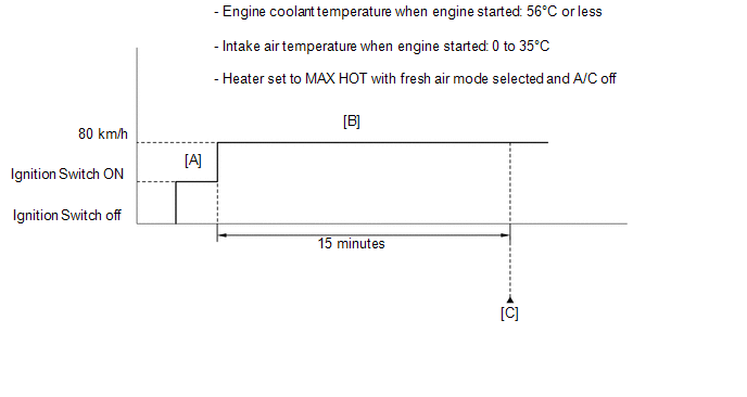
- Stop the engine and allow it to soak.
- Connect the Techstream to the DLC3.
- Turn the ignition switch to ON and turn the Techstream on [A].
- Enter the following menus: Powertrain / Engine / Data List / Primary / Coolant Temp and Intake Air.
- Check that "Coolant Temp" is 56°C (133°F) or less and "Intake Air" is between 0 and 35°C (32 and 95°F).
- Set the heater to MAX HOT with fresh air mode selected and turn the A/C off.
- Start the engine and drive the vehicle at 80 km/h (50 mph) for 15 minutes
[B].
CAUTION:
When performing the confirmation driving pattern, obey all speed limits and traffic laws.
HINT:
- Data can be captured relatively easily by using the snapshot function in the Data List.
- Enter the following menus: Data List / Function / Snapshot Configure / Duration / 5 min.
- Data capture can be started by using the target point function. For example, setting the target point to an engine speed of 4000 rpm and then racing the engine, etc. to raise the engine speed to a speed of 4000 rpm or higher will cause data capture to start.
- After "Coolant Temp" stabilizes, check that "Coolant Temp" is 75°C
(167°F) or higher [C].
HINT:
If "Coolant Temp" is less than 75°C (167°F) while driving the vehicle at 80 km/h (50 mph), inspect the cooling system and thermostat.
CAUTION / NOTICE / HINT
- Read freeze frame data using the Techstream. The ECM records vehicle and driving condition information as freeze frame data the moment a DTC is stored. When troubleshooting, freeze frame data can help determine if the vehicle was moving or stationary, if the engine was warmed up or not, if the air fuel ratio was lean or rich, and other data from the time the malfunction occurred.
- When the DTC is output, check the engine coolant temperature using the Techstream. Enter the following menus: Powertrain / Engine / Data List / Primary / Coolant Temp. If the Coolant Temp value is lower than the actual engine coolant temperature, the engine coolant temperature sensor circuit may be malfunctioning. In this case, check the wire harnesses and connectors (and those connections) between the ECM and the engine coolant temperature sensor first.
PROCEDURE
|
1. |
CHECK ANY OTHER DTCS OUTPUT (IN ADDITION TO DTC P0128) |
(a) Connect the Techstream to the DLC3.
(b) Turn the ignition switch to ON.
(c) Turn the Techstream on.
(d) Enter the following menus: Powertrain / Engine / Trouble Codes.
(e) Read the DTCs.
|
Result |
Proceed to |
|---|---|
|
DTC P0128 is output |
A |
|
DTC P0128 and other DTCs are output |
B |
HINT:
If any DTCs other than P0128 are output, troubleshoot those DTCs first.
| B | .gif) |
GO TO DTC CHART |
|
.gif)
|
2. |
CHECK COOLING SYSTEM |
(a) Check for defects in the cooling system that might cause the system to be too cold, such as abnormal cooling fan operation or any modifications.
| NG | |
REPAIR OR REPLACE COOLING SYSTEM |
|
|
3. |
INSPECT THERMOSTAT |
(a) Inspect the thermostat (See page .gif) ).
).
| NG | |
REPLACE THERMOSTAT |
|
|
4. |
INSPECT ENGINE COOLANT TEMPERATURE SENSOR |
(a) Inspect the engine coolant temperature sensor (See page
).
HINT:
Perform "Inspection After Repair" after replacing the engine coolant temperature
sensor (See page ).
| OK | |
REPLACE ECM |
| NG | |
REPLACE ENGINE COOLANT TEMPERATURE SENSOR |
 Insufficient Coolant Temperature for Closed Loop Fuel Control (P0125)
DESCRIPTION
Refer to DTC P0115 (See page ).
DTC No.
DTC Detection Condition
Trouble Area
P0125
The engine coolant temperature does not r ...
 A/F Sensor Slow Response - Rich to Lean Bank 1 Sensor 1 (P014C,P014D,P015A,P015B)
DESCRIPTION
HINT:
Refer to DTC P2195 (See page ).
DTC No.
DTC Detection Condition
Trouble Area
P014C
The "Rich to Lean response ra ...
Other materials about Toyota Venza:
Open in Front Floor Electrical Key Oscillator Circuit (B27A5)
DESCRIPTION
The certification ECU (smart key ECU assembly) generates a request signal and
sends it to the indoor electrical key oscillator (for front floor). To detect the
key inside the cabin, the indoor electrical key oscillator (for front floor) create ...
Engine Stall History (P1603,P1605)
DESCRIPTION
P1603
After starting the engine, this DTC is stored when the engine stops without the
ignition switch being operated.
Using the Techstream, the conditions present when the DTC was stored can be confirmed
by referring to the freeze frame data ...
Fail-safe Chart
FAIL-SAFE CHART
1. FAIL-SAFE FUNCTION
If the following malfunctions occur, the AWD control ECU will stop the
function of 4WD control system or partly change the function to control
the system.
If a malfunction occurs in the senso ...

0.1279