Toyota Venza: Components
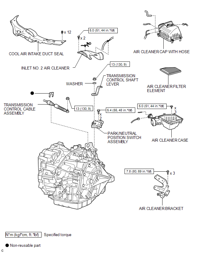
COMPONENTS
ILLUSTRATION

 On-vehicle Inspection
ON-VEHICLE INSPECTION
PROCEDURE
1. INSPECT PARK/NEUTRAL POSITION SWITCH ASSEMBLY OPERATION
(a) Apply the parking brake.
(b) Turn the ignition switch to ON.
(c) Depress the brake pedal and check t ...
Other materials about Toyota Venza:
Security Horn Assembly
Removal
REMOVAL
PROCEDURE
1. REMOVE SECURITY HORN ASSEMBLY
(a) Remove the bolt and disconnect the security horn assembly.
(b) Disconnect the connector and remove the security horn asse ...
On-vehicle Inspection
ON-VEHICLE INSPECTION
PROCEDURE
1. INSPECT ENGINE COOLANT
See page
2. INSPECT ENGINE OIL
See page
3. INSPECT BATTERY
See page
4. INSPECT AIR CLEANER FILTER ELEMENT SUB-ASSEMBLY
(a) Remove the air cleaner filter element sub-assembly.
(b) Visuall ...
Open or Short Circuit in ABS Solenoid Relay Circuit (C0278/11)
DESCRIPTION
The ABS solenoid relay supplies power to the ABS solenoid and TRAC solenoid.
The solenoid relay is turned on 1.5 seconds after the ignition switch is turned
to ON, and is turned off if an open or short in the solenoid is detected by self
diag ...

0.1607