Toyota Venza: Components
COMPONENTS
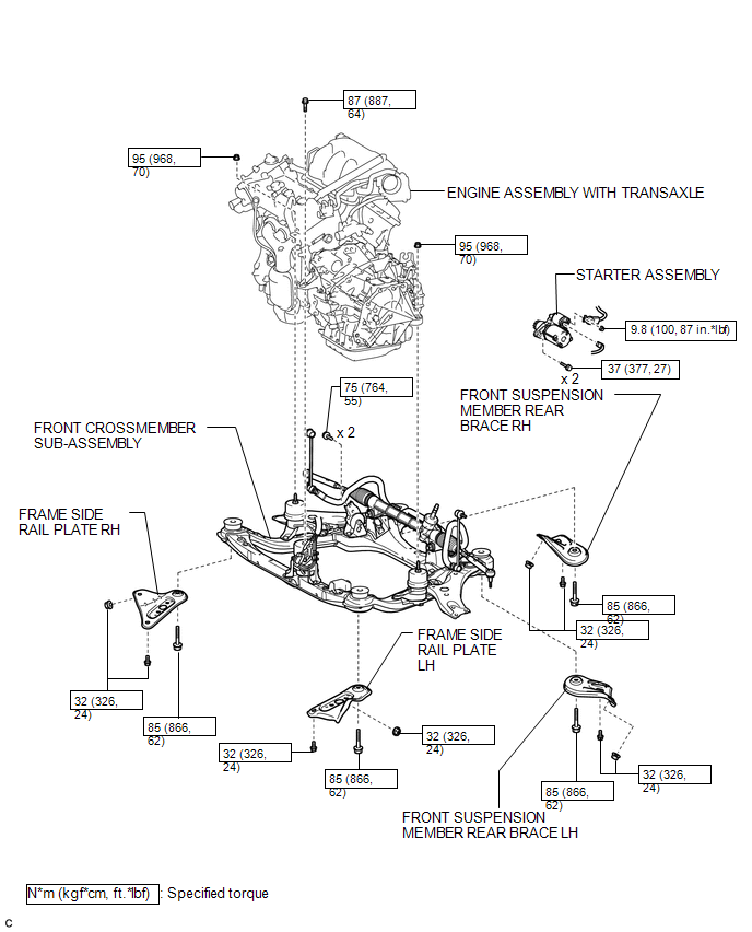
ILLUSTRATION
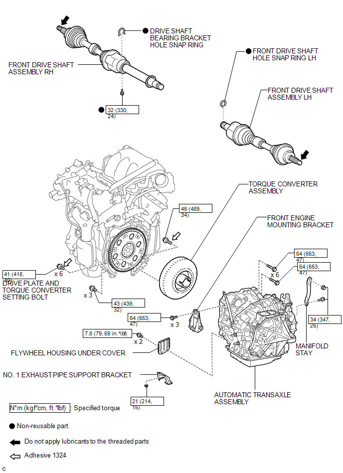
ILLUSTRATION
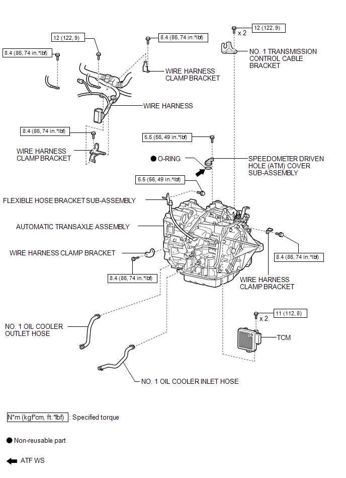
ILLUSTRATION

 Removal
REMOVAL
CAUTION / NOTICE / HINT
NOTICE:
If automatic transaxle assembly parts are replaced, refer to Parts Replacement
Compensation Table to determine if any additional operations are necessary ( ...
Other materials about Toyota Venza:
Differential Oil Seal
Components
COMPONENTS
ILLUSTRATION
Replacement
REPLACEMENT
PROCEDURE
1. DRAIN AUTOMATIC TRANSAXLE FLUID
(a) Remove the No. 2 engine under cover and front fender apron LH.
(b) Using a 6 mm socket hexagon wrench, remove the overflow plug ...
Child restraint systems with a top tether strap
Secure the child restraint using
a seat belt or lower anchors, and do the following.
► Outside
Adjust the head restraint to the upmost position.
► Center
Lower the head restraint to the lowest position.
Open the anchor bracket cover, ...
Data List / Active Test
DATA LIST / ACTIVE TEST
1. ACTIVE TEST
HINT:
Using the Techstream to perform Active Tests allows relays, VSVs, actuators and
other items to be operated without removing any parts. This non-intrusive functional
inspection can be very useful because inter ...

0.1754