Toyota Venza: Components
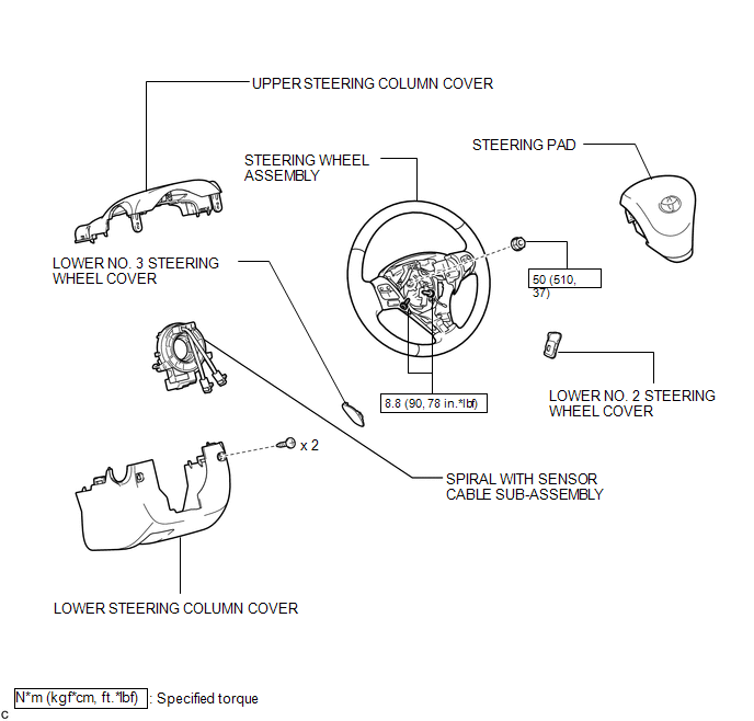
COMPONENTS
ILLUSTRATION

 Installation
INSTALLATION
PROCEDURE
1. INSTALL SPIRAL WITH SENSOR CABLE SUB-ASSEMBLY
(a) Install the spiral with sensor cable sub-assembly (See page
).
NOTICE:
Do not replace the spiral cable with t ...
Other materials about Toyota Venza:
Inspection
INSPECTION
PROCEDURE
1. INSPECT FRONT SHOCK ABSORBER ASSEMBLY
(a) Compress and extend the shock absorber rod 4 or more times.
Standard:
There is no abnormal resistance or sound and operation resistance is
normal.
HINT:
If there i ...
Navigation Antenna
Components
COMPONENTS
ILLUSTRATION
Removal
REMOVAL
PROCEDURE
1. REMOVE INSTRUMENT PANEL SAFETY PAD ASSEMBLY
HINT:
Refer to the procedure up to Remove Instrument Panel Safety Pad Assembly (See
page ).
2. REMOVE NO. 1 SIDE DEFROSTER NOZZLE DUCT ...
Removal
REMOVAL
PROCEDURE
1. REMOVE AIR CONDITIONING UNIT ASSEMBLY
(See page )
2. REMOVE NO. 1 FINISH PANEL MOUNTING BRACKET
3. REMOVE NO. 2 FINISH PANEL MOUNTING BRACKET
4. REMOVE NO. 3 AIR DUCT SUB-ASSEMBLY
5. REMOVE NO. 2 AIR DUCT SUB-ASSEMBLY
...

0.1578