Toyota Venza: Components
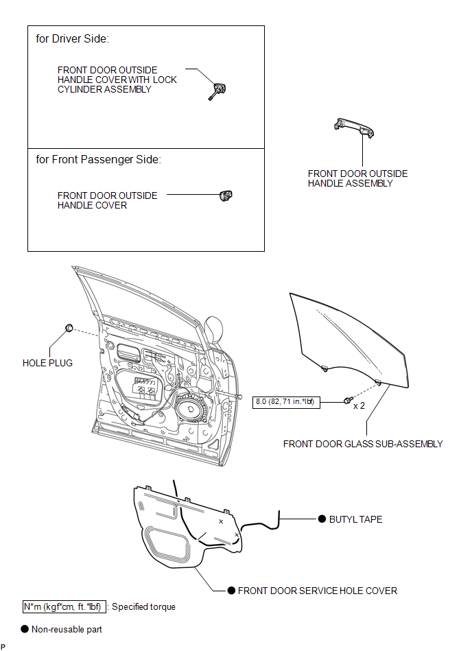
COMPONENTS
ILLUSTRATION
.png)
ILLUSTRATION

 Removal
REMOVAL
PROCEDURE
1. DISCONNECT CABLE FROM NEGATIVE BATTERY TERMINAL
CAUTION:
Wait at least 90 seconds after disconnecting the cable from the negative (-)
battery terminal to disable the SRS sys ...
Other materials about Toyota Venza:
Reassembly
REASSEMBLY
PROCEDURE
1. INSTALL FRONT SIDE MARKER LIGHT BULB
(a) Install the front side marker light bulb to the front side marker light socket.
(b) Turn the front side marker light socket with the front side marker
light bulb in the directi ...
System Diagram
SYSTEM DIAGRAM
Communication Table
Sender
Receiver
Signal
Communication Method
Main Body ECU (Driver Side Junction Block Assembly)
Combination Meter Assembly
Driver side door ...
Data List / Active Test
DATA LIST / ACTIVE TEST
HINT:
Using the Techstream to read the Data List allows the values or states of switches,
sensors, actuators and other items to be read without removing any parts. This non-intrusive
inspection can be very useful because intermitt ...

0.1709