Toyota Venza: Components
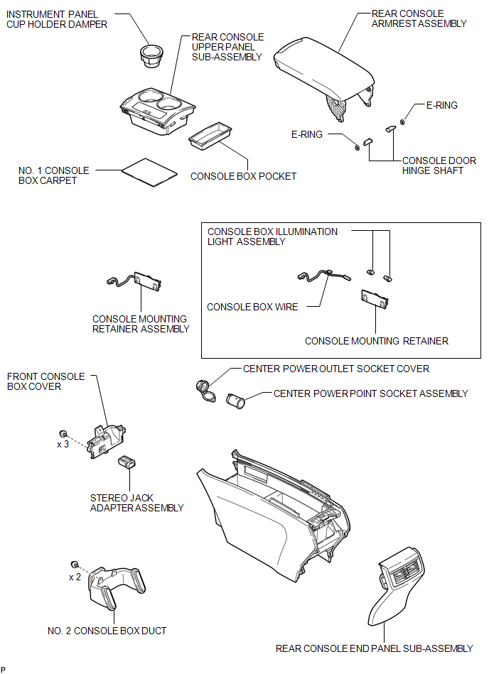
COMPONENTS
ILLUSTRATION
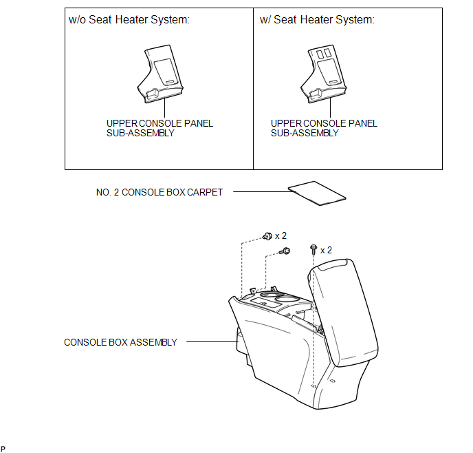
ILLUSTRATION

 Disassembly
DISASSEMBLY
PROCEDURE
1. REMOVE NO. 1 CONSOLE BOX CARPET
(a) Remove the No. 1 console box carpet.
2. REMOVE INSTRUMENT PANEL CUP HOLDER DA ...
Other materials about Toyota Venza:
System Diagram
SYSTEM DIAGRAM
1. AUTOMATIC LIGHT CONTROL SYSTEM
2. LIGHT AUTO TURN-OFF SYSTEM
Communication Table
Transmitter
Receiver
Line
Data Name
Certification ECU (Smart Key ECU Assembly)
Mai ...
System Description
SYSTEM DESCRIPTION
1. ENGINE IMMOBILISER SYSTEM DESCRIPTION
The engine immobiliser system is designed to prevent the vehicle from being stolen.
This system uses the transponder key ECU assembly that stores the key codes of authorized
ignition keys. If an ...
Pressure Control Solenoid "D" Electrical (Shift Solenoid Valve SLT) (P2716)
DESCRIPTION
Refer to DTC P2714 (See page ).
DTC No.
DTC Detection Condition
Trouble Area
P2716
Open or short is detected in shift solenoid valve SLT circuit for 1 second
or more while driving ...

0.1616