Toyota Venza: Components
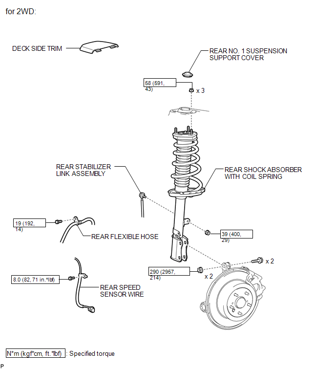
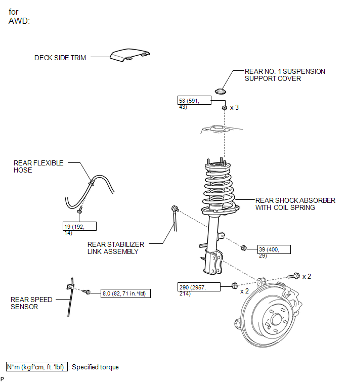
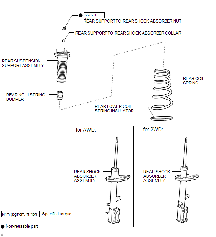
COMPONENTS
ILLUSTRATION
ILLUSTRATION
ILLUSTRATION

 Inspection
INSPECTION
PROCEDURE
1. INSPECT REAR SHOCK ABSORBER ASSEMBLY
(a) Compress and extend the shock absorber rod 4 or more times.
Standard:
There is no abnormal resistance or sound and ...
Other materials about Toyota Venza:
Cursor or Map Rotates when Vehicle Stopped
PROCEDURE
1.
CHECK CONDITION
(a) Check with the customer if the vehicle has been turned by a turntable.
OK:
Vehicle has not been turned by a turntable.
HINT:
If the vehicle is turned on a turntable with ...
Front seats
► Power seat
1. Seat position fore/aft control switch
2. Seatback angle control switch
3. Seat cushion (front) angle control switch (driver’s side only)
4. Vertical height control switch (driver’s side only)
5. Lumbar support control switch
& ...
Rear window wiper and washer
Type A
1. Off
2. Intermittent window wiper operation
3. Normal window wiper operation
4. Washer/wiper dual operation
5. Washer/wiper dual operation
Type B
1. Off
2. Intermittent window wiper operation
3. Normal window wiper operation
4. ...

0.1568