Toyota Venza: Components
COMPONENTS
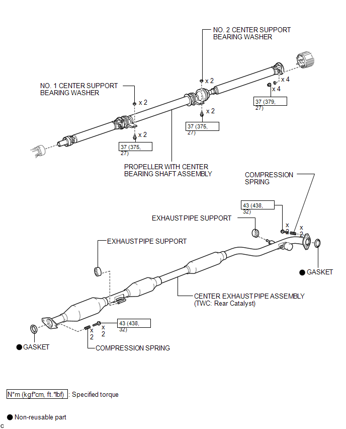
ILLUSTRATION
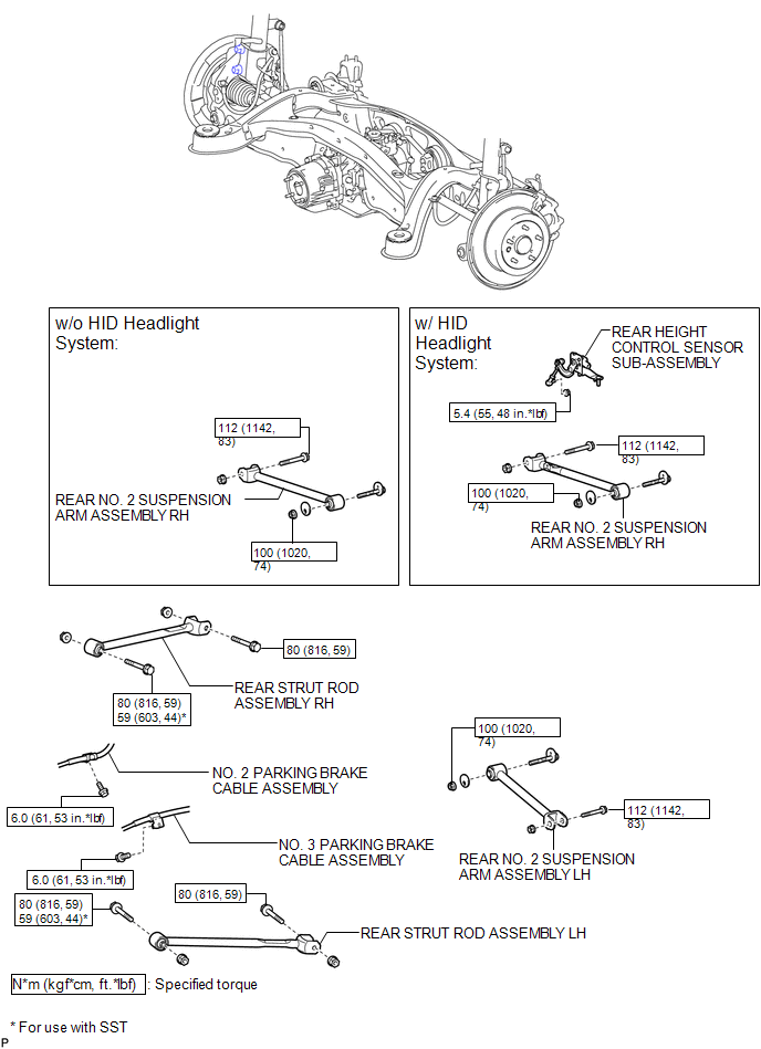
ILLUSTRATION
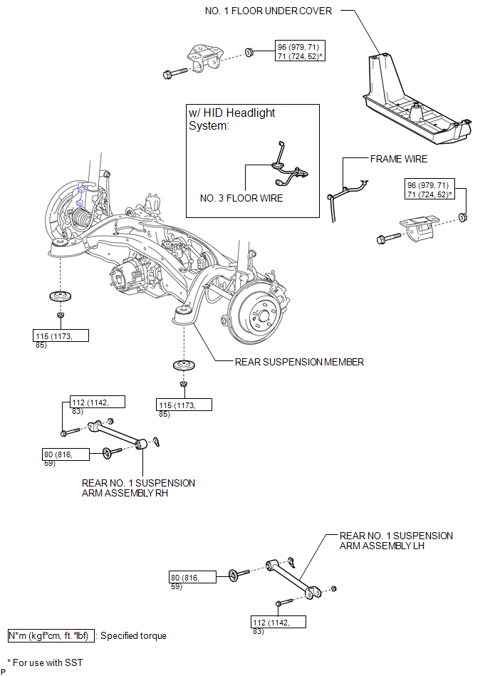
ILLUSTRATION

 Installation
INSTALLATION
PROCEDURE
1. INSTALL REAR NO. 1 SUSPENSION ARM ASSEMBLY LH
(a) Temporarily install the rear No. 1 suspension arm assembly LH to
the rear suspension member with the bolt ...
Other materials about Toyota Venza:
Operation Check
OPERATION CHECK
1. CHECK FUNCTION
(a) Check that the key reminder warning buzzer sounds.
(1) With the driver side door closed, insert the key into the ignition key cylinder
and then make sure that the key is in LOCK or ACC.
(2) Check that the buzzer soun ...
Removal
REMOVAL
CAUTION / NOTICE / HINT
NOTICE:
When disconnecting the steering intermediate shaft assembly and pinion shaft
of steering gear assembly, be sure to place matchmarks before servicing.
PROCEDURE
1. PLACE FRONT WHEELS FACING STRAIGHT AHEAD
2. SECUR ...
TRAC OFF Indicator Light does not Come ON
DESCRIPTION
The skid control ECU is connected to the combination meter via CAN communication.
WIRING DIAGRAM
Refer to TRAC OFF Indicator Light Remains ON (See page
).
PROCEDURE
1.
CHECK CAN COMMUNICATION SYSTEM
(a) Check ...

0.1395