Toyota Venza: Components
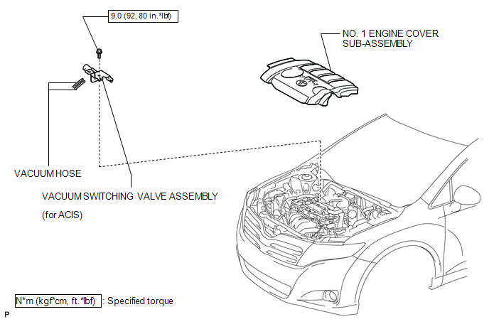
COMPONENTS
ILLUSTRATION
.png)
ILLUSTRATION

 Inspection
INSPECTION
PROCEDURE
1. INSPECT VACUUM SWITCHING VALVE ASSEMBLY (for ACIS)
(a) Measure the resistance according to the value(s) in the table below.
Text in Illustration
...
Other materials about Toyota Venza:
Side Turn Signal Light Assembly
Components
COMPONENTS
ILLUSTRATION
Removal
REMOVAL
CAUTION / NOTICE / HINT
HINT:
Use the same procedure for the RH and LH sides.
The procedure described below is for the LH side.
PROCEDURE
1. REMOVE OUTER MIRROR
2. REMOVE O ...
Operation Check
OPERATION CHECK
1. CHECK POWER DOOR LOCK CONTROL OPERATION
NOTICE:
The following procedure is based on the assumption that the functions have not
been customized using the Techstream.
(a) Check basic functions.
(1) Check that all doors lock when the loc ...
Fuel Sender Gauge Assembly
Components
COMPONENTS
ILLUSTRATION
Removal
REMOVAL
PROCEDURE
1. DISCHARGE FUEL SYSTEM PRESSURE
(a) Discharge fuel system pressure (See page
).
2. DISCONNECT CABLE FROM NEGATIVE BATTERY TERMINAL
NOTICE:
When disconnecting the cable, some syste ...

0.1141