Toyota Venza: Components
COMPONENTS
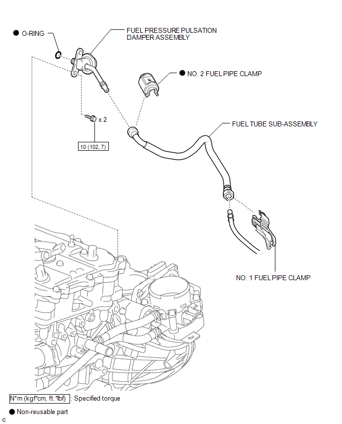
ILLUSTRATION
.png)
ILLUSTRATION
.png)
ILLUSTRATION

 Removal
REMOVAL
PROCEDURE
1. DISCHARGE FUEL SYSTEM PRESSURE
HINT:
See page
2. DISCONNECT CABLE FROM NEGATIVE BATTERY TERMINAL
NOTICE:
When disconnecting the cable, some systems need to be initialized ...
Other materials about Toyota Venza:
Precaution
PRECAUTION
1. PRECAUTION FOR DISCONNECTING CABLE FROM NEGATIVE BATTERY TERMINAL
NOTICE:
After the ignition switch is turned off, the radio and display receiver
assembly records various types of memory and settings. As a result, after
turning ...
Mechanical System Tests
MECHANICAL SYSTEM TESTS
1. STALL SPEED TEST
HINT:
This test is to check the overall performance of the engine and transaxle.
CAUTION:
Driving test should be done on a paved surface (a surface that is not
slippery).
To ensure safety, perfor ...
How To Proceed With Troubleshooting
CAUTION / NOTICE / HINT
HINT:
Perform troubleshooting in accordance with the following flowchart.
*: Use the Techstream.
PROCEDURE
1.
VEHICLE BROUGHT TO WORKSHOP
NEXT
...

0.1644